
CMP-240 · Lesson 2 of 12 · 22 min
Resistors, Ohm's law and Kirchhoff's laws
Lesson 1 described what voltage, current and power are. This lesson introduces the three relationships that let you calculate them in a real circuit: Ohm's law, which relates the voltage across a resistor to the current through it, and Kirchhoff's two laws, which say how currents meet at a node and how voltages add around a loop. Almost every technique in the rest of the course, from nodal analysis to transient response, is built on these three statements.
Jonah's first measurement on the NS-4 is a puzzle. The firmware reports the battery voltage through a pair of resistors feeding the microcontroller's analog-to-digital converter, and on one test board the reading is 0.4 V lower than his multimeter says. Before he can find the cause, he needs to be able to predict what every resistor on that part of the board should be doing.
Resistance and Ohm's law
A resistor opposes the flow of current and turns electrical energy into heat. For many materials, over a useful range, the current through a conductor is proportional to the voltage across it. The constant of proportionality is the resistance R, measured in ohms (Ω), and the relationship is Ohm's law. Its reciprocal, conductance G, is measured in siemens (S) and is convenient when several paths share the same voltage.
Ohm's law uses the passive sign convention: the current reference enters the resistor at its + terminal. With that convention a resistor's power is always positive, because it can only absorb energy. Combining Ohm's law with p = vi gives three equivalent forms of resistor power, and the one to use depends on which quantity you know.
Resistance depends on the material and the shape of the conductor. A uniform conductor of length ℓ, cross-sectional area A and resistivity ρ has resistance R = ρℓ/A. Copper has a resistivity of about 1.7 × 10⁻⁸ Ω·m, so a printed-circuit trace 0.25 mm wide in standard 35 µm copper has about 2 mΩ of resistance per millimetre. That is negligible for a logic signal but matters for a 1.5 A charger path, where a 100 mm trace drops 0.3 V and dissipates nearly half a watt. Resistance also rises with temperature in metals, by about 0.4 percent per degree Celsius for copper.
Elements whose current is proportional to voltage are called linear, and Ohm's law is their defining equation. Many components are not linear: an LED conducts almost nothing until its forward voltage is reached and then conducts heavily, and a thermistor's resistance changes with temperature. Circuit analysis still applies to such parts, but the arithmetic must use their actual characteristics rather than a single resistance.
Real resistors
Surface-mount resistors are identified by a size code and a value code. The NS-4 uses the 0603 size, 1.6 mm × 0.8 mm, for most signals and 1206 for anything that carries real power. Values are chosen from standard series called the E-series, in which each value is a fixed ratio above the last. The E24 series, with 24 values per decade such as 1.0, 1.1, 1.2, 1.3, 1.5, 1.6, 1.8, 2.0, 2.2, 2.4, 2.7, 3.0, 3.3, 3.6, 3.9, 4.3, 4.7, 5.1, 5.6, 6.2, 6.8, 7.5, 8.2 and 9.1, is common for 5 percent and 1 percent parts, and E96 offers 96 values per decade for precision work.
Every resistor has three ratings that matter. The tolerance says how far the actual value may be from the marked value, commonly 1 or 5 percent. The power rating says how much it may dissipate without overheating, about 0.1 W for an 0603 part and 0.25 W for a 1206, with designers usually staying below half the rating. The temperature coefficient says how much the value drifts with temperature, typically 100 parts per million per degree for ordinary thick-film parts. In a roadside box that ranges from −30 °C in winter to +60 °C in summer sun, a 100 ppm/°C part changes by nearly 1 percent across the season.
| Package | Size (mm) | Typical power rating | Used on the NS-4 for |
|---|---|---|---|
| 0402 | 1.0 × 0.5 | 0.063 W | Not used: hard to rework in the field shop |
| 0603 | 1.6 × 0.8 | 0.1 W | Pull-ups, dividers, LED resistors, signal series resistors |
| 0805 | 2.0 × 1.25 | 0.125 W | Gate resistors on the power switches |
| 1206 | 3.2 × 1.6 | 0.25 W | Charger current-sense path, RS-485 termination |
Kirchhoff's current law
Kirchhoff's current law (KCL) states that the algebraic sum of the currents entering a node is zero. Equivalently, the total current flowing into a node equals the total flowing out. KCL is a statement of charge conservation: a node is a point of ideal wire with no room to store charge, so whatever arrives must leave. To apply it, choose a sign convention, for example currents entering the node positive and leaving negative, and write one equation per node.
KCL also applies to any closed boundary drawn around part of a circuit, called a supernode or cut set. If you draw a box around the whole NS-4 board, the current entering on the battery's positive lead must equal the current leaving on the negative lead, however complicated the board inside. That simple fact is why a single current meter in the battery lead measures the entire board's consumption.
Kirchhoff's voltage law
Kirchhoff's voltage law (KVL) states that the algebraic sum of the voltages around any closed loop is zero. It is a statement of energy conservation: a charge carried once around a loop returns to its starting potential, so the energy it gains in sources must equal the energy it loses in loads. To apply KVL, go around the loop in one direction, add each voltage as a rise or a drop according to its polarity, and set the total to zero.
A reliable habit is to sum voltage drops: going around the loop, add a voltage with a plus sign when you enter the element at its + terminal and with a minus sign when you enter at its − terminal. Because KVL holds for every loop, a circuit usually supplies more KVL equations than it needs, and only the independent ones are useful. For a circuit drawn without crossing wires, the independent loops are the meshes, the windows of the drawing, a fact lesson 5 uses for mesh analysis.
Worked problem
An LED status indicator
The NS-4's green status LED is driven from a 3.3 V microcontroller pin through a series resistor to ground. The LED drops 2.1 V at its design current of 4 mA, and the pin's output stage behaves like an ideal 3.3 V source with 25 Ω of internal resistance. Choose a standard E24 resistor and find the actual current and the power in each element.
Show solution
- KVL around the loop, summing drops from the source: 3.3 = i(25 + R) + 2.1.
- \[R = \frac{3.3 - 2.1}{0.004} - 25 = 300 - 25 = 275\ \Omega\]
- The nearest E24 values are 270 Ω and 300 Ω. Choose 270 Ω, which slightly raises the current.
- \[i = \frac{3.3 - 2.1}{25 + 270} = \frac{1.2}{295} = 4.07\ \text{mA}\]
- \[P_R = i^2 R = (0.00407)^2 \times 270 = 4.5\ \text{mW}\]
- \[P_{LED} = 2.1 \times 0.00407 = 8.5\ \text{mW}, \quad P_{pin} = (0.00407)^2 \times 25 = 0.41\ \text{mW}\]
- \[P_{source} = 3.3 \times 0.00407 = 13.4\ \text{mW} = 4.5 + 8.5 + 0.41\]
Answer: A 270 Ω resistor gives about 4.1 mA. The source delivers 13.4 mW and the resistor, LED and pin resistance absorb exactly that amount, which checks the work. The resistor's 4.5 mW is far below an 0603 part's 0.1 W rating.
Maren adds a firmware detail: the status LED is on for 50 ms every 5 seconds, a duty cycle of 1 percent, so its average current is only 41 µA. Without that blinking pattern the LED alone would use about a fifth of the board's sleep current. Small decisions about indicators add up in a battery-powered product.
Series and parallel, briefly
Two elements are in series when they share a node that nothing else connects to, so the same current flows through both. Two elements are in parallel when they connect between the same pair of nodes, so the same voltage appears across both. KVL and Ohm's law show that series resistances add, and KCL and Ohm's law show that parallel conductances add. Lesson 3 develops these combinations and the divider circuits built from them; for now they let us simplify small networks.
Solving a small circuit with KCL, KVL and Ohm's law
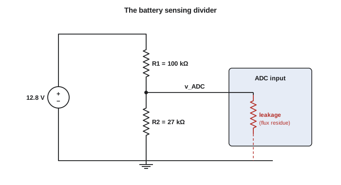
Any linear circuit can be solved by writing KCL at the nodes, KVL around the loops and Ohm's law for every resistor, then solving the resulting equations. This brute-force approach always works but produces many equations. Lessons 4 and 5 show systematic methods that reduce the work. Here the direct method is applied to the battery-sensing circuit that puzzled Jonah.
Worked problem
The battery divider and the missing 0.4 V
The battery connects to ground through R1 = 100 kΩ and R2 = 27 kΩ in series, and the ADC reads the voltage across R2. Firmware scales the reading by (R1 + R2)/R2 to report the battery voltage. Find the expected ADC voltage for a 12.8 V battery. Then suppose the ADC input on the faulty board is leaking, behaving like a 200 kΩ resistance to ground in parallel with R2. Find the new reading and the voltage firmware reports.
Show solution
- No load: the same current flows through both resistors, so i = 12.8/(100 + 27) kΩ = 100.8 µA.
- \[v_{ADC} = iR_2 = 100.8\ \mu\text{A} \times 27\ \text{k}\Omega = 2.72\ \text{V}\]
- Firmware reports 2.72 × 127/27 = 12.8 V, as intended.
- With the leak, R2 is in parallel with 200 kΩ:
- \[R_2' = \frac{27 \times 200}{27 + 200} = 23.8\ \text{k}\Omega\]
- \[v_{ADC} = 12.8 \times \frac{23.8}{100 + 23.8} = 2.46\ \text{V}\]
- \[V_{reported} = 2.46 \times \frac{127}{27} = 11.57\ \text{V}\]
Answer: A 200 kΩ leak would make firmware report about 11.6 V, 1.2 V low. Jonah's error is 0.4 V, so the leak on his board must be much smaller; working backwards, a leak of about 650 kΩ produces a 0.4 V error. A fingerprint of flux residue between the ADC pin and ground can easily have that resistance in damp air, and cleaning the board with isopropyl alcohol cures it.
The lesson from the battery divider is that high-value resistors make a circuit sensitive to small leaks and to the loading of whatever is connected. Ines chose 100 kΩ and 27 kΩ so the divider draws only 100 µA from the battery. The cost of that low current is sensitivity. Lesson 6 makes this trade precise with Thévenin equivalents, and lesson 8 adds a small capacitor that helps the ADC read the divider accurately.
# Battery divider: reported voltage versus an unwanted leakage resistance
R1, R2 = 100e3, 27e3
V_batt = 12.8
scale = (R1 + R2) / R2            # firmware multiplies the ADC voltage by this

def parallel(a, b):
    return a * b / (a + b)

def reported(leak):
    r2 = R2 if leak is None else parallel(R2, leak)
    v_adc = V_batt * r2 / (R1 + r2)
    return v_adc, v_adc * scale

for leak in [None, 10e6, 2e6, 650e3, 200e3]:
    v, rep = reported(leak)
    label = "no leak" if leak is None else "%5.0f kohm leak" % (leak / 1e3)
print("%-16s ADC %.3f V reported %.2f V error %+.2f V" % (label, v, rep, rep - V_batt))no leak ADC 2.721 V reported 12.80 V error -0.00 V 10000 kohm leak ADC 2.715 V reported 12.77 V error -0.03 V 2000 kohm leak ADC 2.693 V reported 12.67 V error -0.13 V 650 kohm leak ADC 2.635 V reported 12.39 V error -0.41 V 200 kohm leak ADC 2.460 V reported 11.57 V error -1.23 V
Power ratings and the dangers of simple mistakes
Ohm's law also tells you when a part will overheat. A resistor connected straight across the 12.8 V battery by mistake dissipates v²/R: a 1 kΩ resistor would see 0.16 W, more than an 0603 part's 0.1 W rating, and would slowly discolour the board; a 100 Ω resistor would see 1.6 W and fail within seconds. Before choosing a resistor for anything connected to the battery, compute its worst-case power, including the highest charging voltage, about 14.6 V on the NS-4.
Common mistakes
MistakeUsing Ohm's law on an LED as if it were a resistor.
InsteadTreat the LED as a roughly constant voltage drop at its operating current and apply Ohm's law only to the resistor.
MistakeMixing up the signs in KVL.
InsteadPick a direction around the loop and a consistent rule, such as adding a voltage when entering its + terminal.
MistakeForgetting that the meter or ADC loads the circuit.
InsteadModel the instrument or input as a resistance and include it, especially with high-value resistors.
MistakeChoosing a resistor value that is not manufactured.
InsteadRound to a standard E-series value and recompute the current with that value.
MistakeChecking a resistor's power only at the nominal supply voltage.
InsteadUse the worst-case voltage, such as the battery's highest charging voltage.
Summary and key terms
- Ohm's law v = iR relates a resistor's voltage and current; resistor power is vi = i²R = v²/R and is always absorbed.
- KCL: the currents entering a node, or any closed boundary, sum to zero.
- KVL: the voltages around any closed loop sum to zero.
- Series resistances add; parallel conductances add.
- High-value resistors save power but make circuits sensitive to leakage and loading.
- Ohm
- The SI unit of resistance, one volt per ampere.
- Siemens
- The SI unit of conductance, the reciprocal of the ohm.
- KCL
- Kirchhoff's current law: the sum of currents entering a node is zero.
- KVL
- Kirchhoff's voltage law: the sum of voltages around a closed loop is zero.
- E-series
- Standard sets of preferred component values, such as E24 and E96.
- Tolerance
- The allowed difference between a component's actual and marked value.
- Linear element
- An element whose current is proportional to its voltage.
Practice problems
Work each problem on paper first, then reveal the answer to check.
A 4.7 kΩ resistor has 3.3 V across it. Find its current and power.
Show answer
i = 0.70 mA; p = 3.3²/4700 = 2.3 mW.
Three currents enter a node: 12 mA, −3 mA and i. Two leave: 5 mA and 6 mA. Find i.
Show answer
12 − 3 + i = 5 + 6, so i = 2 mA.
Around a loop the drops are 5 V, −2 V, v and 1.5 V. Find v.
Show answer
5 − 2 + v + 1.5 = 0, so v = −4.5 V.
What resistor drives a red LED (1.9 V at 5 mA) from 5 V, ignoring source resistance? Choose an E24 value.
Show answer
(5 − 1.9)/0.005 = 620 Ω, which is an E24 value.
Why does a single ammeter in the battery lead measure the whole board's current?
Show answer
KCL applied to a boundary around the board: everything entering on one lead must leave on the other.
Lesson quiz · 5 questions
Score 60% or more to complete this lesson.
Create a free account to save your progress, take quizzes and earn a certificate.