
CMP-240 · Lesson 10 of 12 · 21 min
Second-order response and ringing on signal lines
A circuit with both inductance and capacitance can do something a first-order circuit never does: it can overshoot its final value and oscillate around it before settling. Energy sloshes back and forth between the capacitor's electric field and the inductor's magnetic field, losing a little in the resistance on each swing. On a digital board this behaviour appears as ringing on fast signal edges, as glitches that make a clock input see two edges instead of one, and as overshoot that can push a pin beyond its voltage rating. On long cables a related effect appears as reflections. This lesson introduces second-order response and then shows where the lumped-element assumption from lesson 1 starts to fail.
The NS-5 prototype has a new problem that the NS-4 never had. Its faster microcontroller drives the radar module's clock line through a 9 cm trace, and Jonah's oscilloscope shows the clock overshooting to 4.4 V and ringing below ground before settling. The radar module occasionally misses a configuration command. Ines suspects the ringing, and asks Jonah to find out why it happens and how to stop it.
The series RLC circuit
A logic output switching a trace that ends at an input is, to a first approximation, a series RLC circuit. The output resistance and any series resistor form R, the trace and the pin leads form L, and the input and trace capacitance form C. Applying KVL around the loop and differentiating gives a second-order differential equation. Its behaviour is set by two numbers: the natural frequency ω₀, the frequency at which the circuit would oscillate with no resistance, and the damping ratio ζ, which measures how quickly the resistance removes energy.
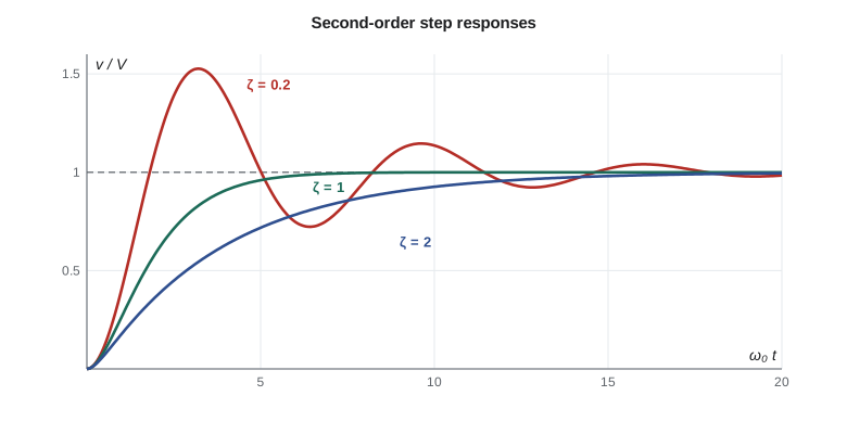
The damping ratio divides the step response into three cases. If ζ > 1 the circuit is overdamped: the voltage rises to its final value without overshoot, more slowly than necessary. If ζ = 1 it is critically damped, the fastest response without overshoot. If ζ < 1 it is underdamped: the voltage overshoots and rings at the damped frequency ω_d = ω₀√(1 − ζ²), with the oscillation decaying inside an exponential envelope. The smaller ζ is, the larger the overshoot and the longer the ringing.
Worked problem
Why the radar clock rings
The microcontroller pin has 18 Ω of output resistance. The 9 cm trace and pin leads have about 60 nH of inductance and the radar input plus the trace about 12 pF of capacitance. Find ω₀, the ringing frequency, ζ and the overshoot on a 0 to 3.3 V edge.
Show solution
- \[\omega_0 = \frac{1}{\sqrt{60\ \text{nH} \times 12\ \text{pF}}} = \frac{1}{\sqrt{7.2 \times 10^{-19}}} = 1.18 \times 10^9\ \text{rad/s}\]
- \[f_0 = \frac{\omega_0}{2\pi} = 188\ \text{MHz}\]
- \[\zeta = \frac{18}{2}\sqrt{\frac{12 \times 10^{-12}}{60 \times 10^{-9}}} = 9 \times 0.01414 = 0.127\]
- \[\text{overshoot} = e^{-\pi(0.127)/\sqrt{1 - 0.016}} = e^{-0.402} = 0.669\]
- \[v_{peak} = 3.3(1 + 0.669) = 5.5\ \text{V (ideal model)}\]
Answer: The circuit is strongly underdamped, with ζ about 0.13. The ideal model predicts an overshoot of two thirds of the step, to about 5.5 V, ringing near 190 MHz. The measured 4.4 V is lower because the input's protection diodes clamp the peak and the trace has extra losses, but the cause is clear: too little resistance for that inductance and capacitance.
Damping with a series resistor
The standard cure is a series resistor at the driver, typically 22 to 47 Ω, which raises R in the damping formula. Critical damping needs R = 2√(L/C), here 2√(60 nH/12 pF) = 141 Ω in total, but that slows the edge considerably. A modest damping ratio of about 0.5 to 0.7 gives a small overshoot and a fast edge. With the pin's 18 Ω, adding a 33 Ω resistor makes R = 51 Ω and ζ = 0.36, cutting the overshoot to about 30 percent; adding 56 Ω gives ζ = 0.52 and about 15 percent. The code below compares several choices. Designers place the resistor right at the driver pin, for reasons the transmission-line section explains.
# Second-order step response of a driver, trace and input: overshoot versus series resistance
import math

L, C, R_out = 60e-9, 12e-12, 18.0
w0 = 1 / math.sqrt(L * C)
print("natural frequency %.0f MHz" % (w0 / 2 / math.pi / 1e6))

def step_response(R, t):
    """Capacitor voltage for a unit step into a series RLC circuit."""
    z = R / 2 * math.sqrt(C / L)
    if z < 1:
        wd = w0 * math.sqrt(1 - z * z)
        return 1 - math.exp(-z * w0 * t) * (math.cos(wd * t) + z / math.sqrt(1 - z * z) * math.sin(wd * t))
    if z == 1:
        return 1 - math.exp(-w0 * t) * (1 + w0 * t)
    s1 = -w0 * (z - math.sqrt(z * z - 1)); s2 = -w0 * (z + math.sqrt(z * z - 1))
    return 1 + (s2 * math.exp(s1 * t) - s1 * math.exp(s2 * t)) / (s1 - s2)

for R_series in (0, 22, 33, 56, 100):
    R = R_out + R_series
    z = R / 2 * math.sqrt(C / L)
    ts = [k * 0.01e-9 for k in range(2000)]
    v = [step_response(R, t) for t in ts]
    peak = max(v)
    t10 = next(t for t, x in zip(ts, v) if x >= 0.1)
    t90 = next(t for t, x in zip(ts, v) if x >= 0.9)
    print("series %3d ohm: zeta %.2f, overshoot %4.0f%%, peak %.2f V, 10-90%% rise %.2f ns"
% (R_series, z, (peak - 1) * 100, 3.3 * peak, (t90 - t10) * 1e9))natural frequency 188 MHz series 0 ohm: zeta 0.13, overshoot 67%, peak 5.51 V, 10-90% rise 0.95 ns series 22 ohm: zeta 0.28, overshoot 40%, peak 4.61 V, 10-90% rise 1.11 ns series 33 ohm: zeta 0.36, overshoot 30%, peak 4.28 V, 10-90% rise 1.19 ns series 56 ohm: zeta 0.52, overshoot 15%, peak 3.78 V, 10-90% rise 1.43 ns series 100 ohm: zeta 0.83, overshoot 1%, peak 3.33 V, 10-90% rise 2.21 ns
The table shows the trade. With no series resistor the edge is fastest but overshoots wildly. A 33 Ω resistor brings the overshoot down to about 30 percent while keeping the rise time near 1 ns, still far faster than the radar's 4 MHz configuration clock needs. Ines chooses 56 Ω for the NS-5, giving about 15 percent overshoot, and the missed commands stop.
When wires stop being wires
The lumped-element model assumes a signal arrives everywhere on a connection at the same instant. In reality signals travel at a finite speed, about 15 to 20 cm per nanosecond on a circuit board, roughly half to two thirds of the speed of light. When the time a signal takes to travel along a connection becomes comparable to its rise time, the connection must be treated as a transmission line. A common rule of thumb is that a trace needs transmission-line treatment when its length exceeds about one sixth of the distance the signal travels during the rise time.
For the radar clock, a 1 ns edge travels about 15 cm, so the critical length is about 2.5 cm and the 9 cm trace qualifies as a transmission line. The lumped RLC model above still gives the right picture of the ringing, but the more accurate view says that the edge travels down the trace, reflects from the high-impedance input and travels back, and the reflections add up to the observed ringing.
Characteristic impedance and reflections
A transmission line, such as a trace over a ground plane or a twisted pair, has inductance and capacitance spread along its length. A signal travelling along it sees not a capacitor or an inductor but a pure resistance called the characteristic impedance, Z₀ = √(L′/C′), where L′ and C′ are the inductance and capacitance per unit length. Typical board traces are designed for 50 Ω, and twisted-pair cables such as RS-485 and Ethernet are around 100 to 120 Ω.
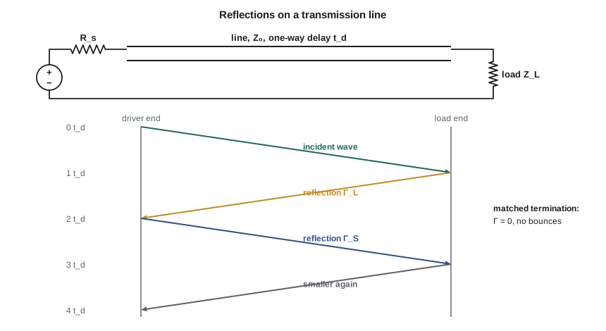
When a travelling wave reaches a point where the impedance changes, part of it reflects. The reflection coefficient Γ = (Z_L − Z₀)/(Z_L + Z₀) gives the fraction of the voltage that comes back. An open end (Z_L very large) reflects the whole wave with the same sign, doubling the voltage there; a short (Z_L = 0) reflects it inverted; a matched load (Z_L = Z₀) absorbs it completely with no reflection. A CMOS input is nearly an open circuit, which is why an unterminated line overshoots.
Termination
Two termination methods are common. Series termination places a resistor at the driver so that the driver's output resistance plus the resistor equals Z₀. The wave launched down the line is then half the final voltage; it doubles on reflection at the open receiver, giving the full voltage there, and the returning wave is absorbed by the matched source. This is why the series resistor goes at the driver, and it uses no extra power. Parallel termination places a resistor equal to Z₀ across the far end, absorbing the wave on arrival; it gives the cleanest result but draws current continuously. It is the standard choice for multi-drop buses where several receivers share one line.
Worked problem
Terminating the RS-485 link to the cabinet
The NS-4 talks to the roadside cabinet over a 40 m twisted pair with Z₀ = 120 Ω, carrying RS-485 at 115.2 kbit/s. Signals travel along the cable at about 0.66c. Find the one-way delay, decide whether the cable is a transmission line for the driver's 50 ns edges, and compute the reflection from an unterminated end and from a 120 Ω terminator.
Show solution
- \[v_p = 0.66 \times 3 \times 10^8 = 1.98 \times 10^8\ \text{m/s}, \qquad t_d = \frac{40}{1.98 \times 10^8} = 202\ \text{ns}\]
- \[\ell_{crit} = \frac{50\ \text{ns} \times 0.198\ \text{m/ns}}{6} = 1.65\ \text{m} \ll 40\ \text{m}\]
- \[\Gamma_{open} = \frac{\infty - 120}{\infty + 120} = +1, \qquad \Gamma_{120} = \frac{120 - 120}{120 + 120} = 0\]
Answer: The cable is about 25 times longer than the critical length, so it is very much a transmission line. Unterminated, every edge would bounce back and forth with a round trip of about 400 ns, smearing the start of each bit. A 120 Ω resistor across each end of the pair absorbs the waves; RS-485 practice is to terminate both ends of the cable, which is why the NS-4 board and the cabinet each carry a 120 Ω resistor that can be switched in.
What this means for digital design
Ringing and reflections are set by edge speed, not clock frequency. A slow 1 MHz signal produced by a modern microcontroller with 1 ns edges rings just as badly as a fast one. Practical habits follow: use the slowest edge rate that meets timing, since many microcontrollers let firmware choose the drive strength; keep fast traces short and over a continuous ground plane; add a series resistor at the driver of any clock or fast signal longer than a few centimetres; and terminate long cables at their impedance. ELE-203 and later courses treat transmission lines and signal integrity in much more depth.
Common mistakes
MistakeThinking ringing depends on the clock frequency.
InsteadIt depends on the edge rate and the trace's inductance and capacitance; a slow clock with fast edges still rings.
MistakePutting a series termination resistor at the receiver.
InsteadSeries termination works at the driver, where it absorbs the returning reflection.
MistakeChoosing critical damping for every signal.
InsteadCritical damping slows edges; a damping ratio of about 0.5 to 0.7 balances overshoot and speed.
MistakeTreating a long cable as a simple wire.
InsteadWhen its delay is comparable to the edge time, treat it as a transmission line and terminate it.
MistakeTerminating only one end of an RS-485 cable.
InsteadTerminate both ends of the bus with resistors equal to the cable impedance.
Summary and key terms
- Series RLC circuits have natural frequency ω₀ = 1/√(LC) and damping ratio ζ = (R/2)√(C/L).
- Underdamped circuits (ζ < 1) overshoot by e^(−πζ/√(1 − ζ²)) and ring at ω₀√(1 − ζ²).
- A series resistor at the driver damps ringing on fast signals at a small cost in rise time.
- Connections longer than about one sixth of the edge's travel distance behave as transmission lines with characteristic impedance Z₀.
- Impedance changes reflect part of a wave (Γ = (Z_L − Z₀)/(Z_L + Z₀)); series or parallel termination prevents reflections.
- Natural frequency
- The frequency ω₀ = 1/√(LC) at which an undamped LC circuit oscillates.
- Damping ratio
- The dimensionless number ζ that determines whether a second-order circuit overshoots.
- Overshoot
- The amount by which a step response exceeds its final value.
- Ringing
- Decaying oscillation following a fast edge in an underdamped circuit.
- Transmission line
- A connection long enough that signal travel time must be taken into account.
- Characteristic impedance
- The ratio of voltage to current for a wave travelling along a transmission line.
- Termination
- A resistor that matches a line's characteristic impedance to prevent reflections.
Practice problems
Work each problem on paper first, then reveal the answer to check.
Find ω₀ and f₀ for L = 1 µH and C = 1 nF.
Show answer
ω₀ = 1/√(10⁻¹⁵) ≈ 3.16 × 10⁷ rad/s; f₀ ≈ 5.0 MHz.
What resistance gives critical damping with L = 1 µH and C = 1 nF?
Show answer
R = 2√(L/C) = 2√1000 ≈ 63 Ω.
What is the overshoot for ζ = 0.5?
Show answer
e^(−π(0.5)/0.866) ≈ 0.163, about 16 percent.
A 50 Ω line ends in a 150 Ω load. What is the reflection coefficient?
Show answer
(150 − 50)/(150 + 50) = 0.5.
Is a 3 cm trace a transmission line for 5 ns edges at 15 cm/ns?
Show answer
Critical length ≈ 5 × 15/6 = 12.5 cm, so 3 cm is not; lumped analysis is fine.
Lesson quiz · 5 questions
Score 60% or more to complete this lesson.
Create a free account to save your progress, take quizzes and earn a certificate.