
CMP-240 · Lesson 12 of 12 · 23 min
AC power, frequency response and filters
The last lesson of the course puts impedance to work. It begins with power in AC circuits, where voltage and current may be out of phase and the simple product vi no longer gives the average power. It then looks at frequency response, the way a circuit's output changes as the input frequency is swept, and at the Bode plot that engineers use to show it. Filters, circuits designed to pass some frequencies and block others, are the payoff: the RC low-pass filter in front of an ADC, the high-pass coupling capacitor, and the LC filter that keeps a switching regulator's ripple away from a sensitive radio. The lesson ends by collecting the design decisions Jonah and Ines made for the NS-5 board.
Power in AC circuits
For sinusoidal steady state, the instantaneous power p(t) = v(t)i(t) oscillates at twice the signal frequency. Its average over a cycle is what heats a resistor or drains a battery. If the voltage and current phasors have RMS magnitudes V and I and the current lags the voltage by angle θ, the average or real power is V I cos θ. The factor cos θ is the power factor. A resistor has θ = 0 and a power factor of 1; an ideal capacitor or inductor has θ = ±90° and absorbs no average power at all, storing energy in one half-cycle and returning it in the next.
The quantity Q, measured in volt-amperes reactive (var), describes the energy that sloshes back and forth without being used; S, measured in volt-amperes (VA), is the apparent power, the product of the RMS voltage and current. Power factor matters for anything plugged into the mains. A supply with a poor power factor draws more current than its real power needs, which heats wiring and transformers, so power supplies above a certain size must include power factor correction. The roadside cabinet's 24 V supply, which powers the cabinet's own equipment, is rated in both watts and volt-amperes for exactly this reason.
For a single element the formulas reduce to familiar ones. A resistor absorbs I²R of real power, using RMS current, and an inductor or capacitor absorbs only reactive power, I²X. The statement that total power in a circuit sums to zero, from lesson 1, holds separately for real power and for reactive power, which gives two checks on any AC calculation.
Frequency response and transfer functions
A circuit's frequency response is its output phasor divided by its input phasor, as a function of frequency. This complex ratio is the transfer function H(jω). Its magnitude |H| says how much the circuit scales a sinusoid at that frequency, and its angle says how much it shifts the phase. For a voltage divider made of impedances, the transfer function is simply the divider ratio with ω left as a variable.
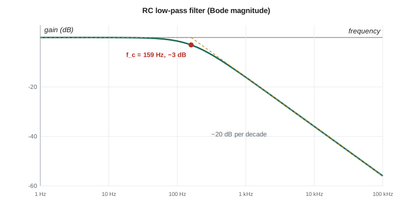
The RC low-pass filter takes its output across the capacitor. At low frequencies the capacitor is nearly open and the output follows the input; at high frequencies the capacitor is nearly a short and the output falls toward zero. The cutoff frequency f_c = 1/(2πRC) marks the boundary: there the magnitude is 1/√2, about 0.707, and the phase is −45°. Well above cutoff the magnitude falls in inverse proportion to frequency. Swapping the resistor and capacitor gives the RC high-pass filter, H = jωRC/(1 + jωRC), which blocks DC and passes high frequencies; a coupling capacitor in series with an input is a high-pass filter.
Decibels and Bode plots
Because filters change gain by factors of thousands across a wide range of frequencies, engineers plot gain on logarithmic scales. Gain in decibels is 20 log₁₀ |H| for voltage ratios. A factor of 10 is 20 dB, a factor of 2 is about 6 dB, 0.707 is −3 dB and 0.1 is −20 dB. A Bode plot draws the magnitude in decibels and the phase in degrees against frequency on a logarithmic axis. On a Bode plot the RC low-pass filter becomes two straight-line asymptotes: flat at 0 dB below cutoff, and falling at −20 dB per decade above it, meeting at the cutoff frequency, where the true curve is 3 dB below the corner.
Filtering before the ADC
Firmware samples the NS-5's analog inputs at fixed rates: the battery and thermistor once a second, but the loop-detector signal, which shows each vehicle as a change in a sensing coil's oscillator, at 1 kHz. Sampling theory, covered in ELE-250, says that any signal content above half the sampling rate, the Nyquist frequency, aliases: it shows up in the samples as a false lower frequency. An anti-aliasing filter before the ADC removes that content. A single RC stage is the simplest choice and, with the reservoir capacitor already on most ADC inputs, often costs only one resistor.
Worked problem
An anti-aliasing filter for the loop detector input
The loop-detector signal of interest lies below 50 Hz and is sampled at 1 kHz, so the Nyquist frequency is 500 Hz. Choose R and C for an RC low-pass filter with cutoff near 160 Hz, using a 100 nF capacitor, and find the attenuation at 50 Hz, 500 Hz and at 60 Hz mains hum's harmonic at 900 Hz, which would alias to 100 Hz.
Show solution
- \[R = \frac{1}{2\pi f_c C} = \frac{1}{2\pi(160)(100 \times 10^{-9})} = 9.95\ \text{k}\Omega \;\Rightarrow\; 10\ \text{k}\Omega,\ f_c = 159\ \text{Hz}\]
- \[|H(50)| = \frac{1}{\sqrt{1 + (50/159)^2}} = 0.954 \ (-0.4\ \text{dB})\]
- \[|H(500)| = \frac{1}{\sqrt{1 + (500/159)^2}} = 0.303 \ (-10.4\ \text{dB})\]
- \[|H(900)| = \frac{1}{\sqrt{1 + (900/159)^2}} = 0.174 \ (-15.2\ \text{dB})\]
Answer: A 10 kΩ, 100 nF filter passes the vehicle signals almost untouched, losing less than 5 percent at 50 Hz, and reduces content at the Nyquist frequency to 30 percent and the 900 Hz hum harmonic to about 17 percent. A single pole falls off slowly, at 20 dB per decade, so firmware also averages several samples, which acts as a further digital filter. Applications that need sharper filtering use second-order active filters built from op-amps, or sample much faster and filter digitally.
Second-order filters and resonance
An LC filter, an inductor in series with a capacitor across the output, is second order: above its resonant frequency its magnitude falls at −40 dB per decade, twice as fast as an RC stage, and it wastes almost no energy because inductors and capacitors are lossless in the ideal case. Near the resonant frequency f₀ = 1/(2π√(LC)) its response depends on the damping. With little resistance the filter peaks at resonance, amplifying signals there by the quality factor Q, which for a series RLC circuit is (1/R)√(L/C) = 1/(2ζ). A large peak can turn a filter into an amplifier for exactly the noise it was meant to remove, so LC filters are usually damped, for example with a capacitor that has some ESR.
Worked problem
Keeping regulator ripple out of the radio
The buck regulator switches at 400 kHz and leaves 20 mV peak-to-peak of ripple on the 3.3 V rail. The radio module needs less than 1 mV. Ines adds a 10 µH inductor in series with the radio's supply and a 22 µF capacitor (about 10 µF effective at 3.3 V) at its pin. Find the filter's resonant frequency and the ideal attenuation at 400 kHz.
Show solution
- \[f_0 = \frac{1}{2\pi\sqrt{10 \times 10^{-6} \times 10 \times 10^{-6}}} = \frac{1}{2\pi \times 10^{-5}} = 15.9\ \text{kHz}\]
- Well above f₀ the magnitude is about (f₀/f)²:
- \[|H(400\ \text{kHz})| \approx \Big(\frac{15.9}{400}\Big)^2 = 1.58 \times 10^{-3} \ (-56\ \text{dB})\]
- \[v_{ripple,radio} \approx 20\ \text{mV} \times 1.58 \times 10^{-3} = 0.032\ \text{mV}\]
Answer: In the ideal model the filter reduces the ripple from 20 mV to about 0.03 mV, far below the 1 mV requirement. The real reduction is smaller, perhaps 30 to 40 dB, because the capacitor's ESL and the inductor's own capacitance limit the attenuation at high frequencies, but even 30 dB gives 0.6 mV. The resonance at 16 kHz is well below the switching frequency and is damped by the capacitor's ESR and the radio's load current.
# Bode data for the RC anti-aliasing filter and the LC supply filter
import math

def rc_lowpass(f, R, C):
    return 1 / complex(1, 2 * math.pi * f * R * C)

def lc_lowpass(f, L, C, R):
    w = 2 * math.pi * f
    return 1 / complex(1 - w * w * L * C, w * R * C)

def db(h):
    return 20 * math.log10(abs(h))

print("RC low-pass, 10 kohm and 100 nF (fc = %.0f Hz)" % (1 / (2 * math.pi * 10e3 * 100e-9)))
for f in (10, 50, 159, 500, 900, 5000):
    h = rc_lowpass(f, 10e3, 100e-9)
    print("  %5d Hz: %6.1f dB, phase %6.1f deg" % (f, db(h), math.degrees(math.atan2(h.imag, h.real))))

L, C = 10e-6, 10e-6
for R in (0.02, 0.3, 1.0):           # series resistance: inductor DCR plus capacitor ESR
    f0 = 1 / (2 * math.pi * math.sqrt(L * C))
    Q = math.sqrt(L / C) / R
    peak = max(db(lc_lowpass(f, L, C, R)) for f in [f0 * (0.8 + 0.001 * k) for k in range(400)])
    print("LC filter R = %.2f ohm: f0 = %.1f kHz, Q = %.1f, resonant peak %+.1f dB, at 400 kHz %.1f dB"
% (R, f0 / 1e3, Q, peak, db(lc_lowpass(400e3, L, C, R))))RC low-pass, 10 kohm and 100 nF (fc = 159 Hz)
10 Hz: -0.0 dB, phase -3.6 deg
50 Hz: -0.4 dB, phase -17.4 deg
159 Hz: -3.0 dB, phase -45.0 deg
500 Hz: -10.4 dB, phase -72.3 deg
900 Hz: -15.2 dB, phase -80.0 deg
5000 Hz: -29.9 dB, phase -88.2 deg
LC filter R = 0.02 ohm: f0 = 15.9 kHz, Q = 50.0, resonant peak +34.0 dB, at 400 kHz -56.0 dB
LC filter R = 0.30 ohm: f0 = 15.9 kHz, Q = 3.3, resonant peak +10.6 dB, at 400 kHz -56.0 dB
LC filter R = 1.00 ohm: f0 = 15.9 kHz, Q = 1.0, resonant peak +1.1 dB, at 400 kHz -56.0 dBThe LC results show the damping trade. With only 20 mΩ of resistance the filter's Q is 50 and it amplifies any noise near 16 kHz by about 34 dB, a real risk because the radar's pulses contain energy there. With 0.3 Ω the peak is a mild 10 dB, and with 1 Ω it almost disappears, all while the attenuation at 400 kHz stays above 50 dB. Ines chooses a capacitor with about 0.3 Ω of ESR in parallel with the low-ESR ceramic, a common way to damp an LC filter without wasting DC power.
Capstone: the NS-5 board decisions
Over the term, Jonah's analysis touched every part of the board, and the NS-5's design review lists the results. The energy budget from lesson 1 showed that the radar's listening duty cycle, not the radio, dominates battery life. The battery divider from lessons 2 and 6 gets a 100 nF reservoir capacitor, and the board gets a cleaning step after assembly to remove flux. The service button keeps its 47 kΩ pull-up and gains a 22 nF debounce capacitor with a Schmitt input (lessons 3 and 9). The I²C pull-ups stay at 2.2 kΩ, with a note that no module may add its own (lessons 3 and 9). The radar's 5 V output uses a divider with 1 percent resistors (lesson 3).
The analog section changes too. The thermistor network was solved with nodal analysis (lesson 4) and gains a buffer (lesson 7). The charger's current sense uses a gain of 33 (lesson 7), and the low-battery cutoff gets 0.8 V of hysteresis (lesson 7). Decoupling uses 100 nF and 1 nF capacitors beside each chip (lessons 8 and 11), and the relay keeps its flyback diode (lesson 8). The radar clock gets a 56 Ω series resistor (lesson 10), the RS-485 cable is terminated at both ends (lesson 10), the loop-detector input gets a 159 Hz anti-aliasing filter, and the radio's supply gets a damped LC filter (lesson 12). None of these decisions needed anything beyond the circuit laws in this course, applied carefully with real component values and worst-case thinking. That is what makes circuit analysis one of the most practical tools a computer engineer has.
Common mistakes
MistakeComputing AC power as the product of peak voltage and peak current.
InsteadUse RMS values and the power factor: P = V_rms I_rms cos θ.
MistakeExpecting a capacitor or inductor to consume average power.
InsteadIdeal reactive elements absorb only reactive power; real power is lost only in resistance.
MistakeReading −3 dB as 'half the voltage'.
Instead−3 dB is a voltage ratio of 0.707, which is half the power; half the voltage is −6 dB.
MistakeDesigning an LC filter without considering resonance.
InsteadCheck the Q; damp the filter so it does not amplify noise at its resonant frequency.
MistakeAssuming a single RC stage removes all aliasing.
InsteadA first-order filter falls only 20 dB per decade; combine it with faster sampling, digital filtering or a higher-order filter.
Summary and key terms
- Average AC power is V_rms I_rms cos θ; reactive elements store and return energy without absorbing average power.
- The transfer function H(jω) gives a circuit's gain and phase shift at each frequency.
- The RC low-pass filter has cutoff f_c = 1/(2πRC), where it is −3 dB with −45° phase, and falls at −20 dB per decade above it.
- Bode plots show gain in decibels and phase against logarithmic frequency; straight-line asymptotes approximate them.
- Second-order LC filters fall at −40 dB per decade but must be damped so their resonance does not amplify noise.
- Power factor
- The ratio of real power to apparent power, cos θ for sinusoids.
- Apparent power
- The product of RMS voltage and RMS current, measured in volt-amperes.
- Transfer function
- The ratio of output phasor to input phasor as a function of frequency.
- Cutoff frequency
- The frequency at which a filter's gain has fallen by 3 dB from its passband value.
- Decibel
- A logarithmic unit of ratio; for voltages, 20 log₁₀ of the ratio.
- Bode plot
- A pair of plots of gain in decibels and phase against frequency on a logarithmic axis.
- Quality factor
- A measure of the sharpness of a resonance, Q = 1/(2ζ) for a second-order circuit.
- Anti-aliasing filter
- A low-pass filter that removes content above half the sampling rate before an ADC.
Practice problems
Work each problem on paper first, then reveal the answer to check.
A load draws 2 A RMS from 120 V RMS with the current lagging by 30°. Find P, Q and S.
Show answer
P = 240 × 0.866 = 208 W; Q = 120 var; S = 240 VA.
Find the cutoff frequency of 4.7 kΩ and 10 nF.
Show answer
1/(2π × 4.7 × 10³ × 10 × 10⁻⁹) ≈ 3.39 kHz.
What is the gain of an RC low-pass filter one decade above its cutoff?
Show answer
About −20 dB (exactly −20.04 dB).
Express a voltage gain of 0.01 in decibels.
Show answer
−40 dB.
Find the resonant frequency and Q of L = 22 µH, C = 47 µF and R = 0.1 Ω.
Show answer
f₀ = 1/(2π√(1.034 × 10⁻⁹)) ≈ 4.95 kHz; Q = (1/0.1)√(22 µH/47 µF) = 10 × 0.684 ≈ 6.8.
Lesson quiz · 5 questions
Score 60% or more to complete this lesson.
Create a free account to save your progress, take quizzes and earn a certificate.