
CIV-499 · Lesson 6 of 12 · 19 min
Substructure and foundations
The superstructure is the part of a bridge that people see; the substructure is the part that decides whether it is still level in 75 years. For the Kestrel Creek crossing, the abutments must carry the bridge reactions and the approach fill, resist the lateral earth pressure of the fill behind them, stay clear of the creek as it moves, and sit on ground that the earlier courses have shown to be soft and full of pressurized water. This lesson chooses the foundation type, sizes the piles, sets out the bearings and joints, and protects the abutments against scour.
Abutment layout
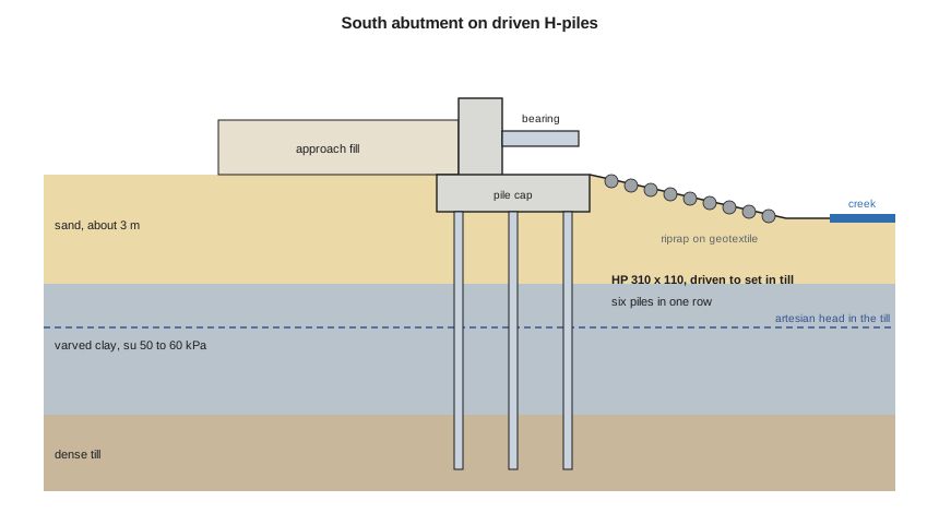
Each abutment is a reinforced concrete seat on a pile cap, with short wingwalls that retain the approach fill and a ballast wall behind the bearings. The abutments sit on the valley sides, about 8 m back from the top of the creek bank, outside the zone where the master plan expects the channel to migrate over the design life. The approach fill behind each abutment is light: the south abutment retains about 1.6 m of fill, the north less than 0.5 m, as lesson 8 shows. Setting the abutments back lengthens the span by a few metres but removes them from the scour zone and the regulated channel, and it was part of what made the single-span concepts score well in lesson 4.
Choosing the foundation type
Three foundation types were considered. Spread footings on the sand would be cheapest, but the varved clay beneath the sand would consolidate under the abutment and the approach fill, and the foundation course showed how easily differential settlement in this clay exceeds what a structure tolerates. Drilled shafts into the till would carry large loads, but drilling an open hole into artesian till next to a creek invites a blowout: water and soil flowing up the hole, loss of ground and a sediment release into the creek that the permit would not allow. Driven steel H-piles displace little soil, leave no open hole, and can be driven into the till to a set without dewatering. The team, with Dr. Kowalczyk's agreement, chooses H-piles.
| Option | For | Against | Decision |
|---|---|---|---|
| Spread footings on sand | cheapest; simple | consolidation of the varved clay below; settlement under fill | rejected |
| Drilled shafts into till | high capacity; few elements | open hole in artesian till near the creek; blowout and sediment risk | rejected |
| Driven steel H-piles | no open hole; drive to set in till; proven locally | noise and vibration; corrosion allowance; driving records needed | chosen |
Pile capacity
The axial resistance of a pile is the sum of the shaft resistance along its length and the toe resistance at its tip. Steel H-piles in soil tend to plug between the flanges, so the team calculates resistance on the boxed perimeter and boxed toe area, a common simplification for H-piles driven into dense material. In the sand and the till, the unit shaft resistance is β times the vertical effective stress; in the clay, it is α times the undrained strength.
The values of β, α and the toe resistance follow the foundation course, with the clay strength from the new field vane tests and the till parameters from the earlier work. Because the till is dense and the piles are driven to a set, the toe and the till shaft together provide most of the resistance; the clay contributes a useful share and the loose sand very little.
# Abutment foundations: factored reactions, steel H-pile capacity in the CIV-340 ground model,
# pile count, and the thermal movement the bearings and joints must take
import math
UNITS = "SI"
SI = UNITS == "SI"
if SI:
    L, wD, wL = 36.0, 20.0, 14.4                 # m, kN/m, kN/m
    abut_dead = 1450.0                           # abutment, wingwalls and backfill weight on the piles, kN
    R = 1.20 * (wD * L / 2 + abut_dead) + 1.70 * wL * L / 2
    # HP 310 x 110: perimeter of the boxed section and toe area
    per, Atoe = 4 * 0.31, 0.31 * 0.31
    layers = [("sand", 0.0, 3.0, "beta", 0.30, 18.0), ("varved clay", 3.0, 10.0, "alpha", 0.90, 55.0),
              ("dense till", 10.0, 13.0, "beta", 0.50, 21.0)]   # name, top, bottom (m below pile cap), method, coeff, gamma' or su
    qtoe = 6000.0                                # kPa, unit toe resistance in the dense till
    phi = 0.40                                   # geotechnical resistance factor, static analysis
    alphaT, dT = 12e-6, 70.0                     # 1/degC, design temperature range for the steel
    u, uf = "kN", "m"
else:
    L, wD, wL = 120.0, 1.37, 1.08
    abut_dead = 390.0                            # kips
    R = 1.0 * (wD * L / 2 + abut_dead) + 1.0 * wL * L / 2        # service load for ASD
    per, Atoe = 4 * 1.02, 1.02 * 1.02            # HP 12 x 74, boxed (ft)
    layers = [("sand", 0.0, 10.0, "beta", 0.30, 0.114), ("varved clay", 10.0, 33.0, "alpha", 0.90, 1.15),
              ("dense till", 33.0, 43.0, "beta", 0.50, 0.133)]  # ksf for su, kcf for gamma'
    qtoe = 125.0                                 # ksf
    FS = 3.0                                     # factor of safety, static analysis without a load test
    alphaT, dT = 6.5e-6, 125.0                   # 1/degF
    u, uf = "kips", "ft"
shaft = 0.0; sv = 0.0
for name, top, bot, how, c, p in layers:
    h = bot - top
    if how == "beta":
        mid = sv + p * h / 2
        q = c * mid * per * h
        sv += p * h
    else:
        q = c * p * per * h
        sv += (8.5 if SI else 0.054) * h         # effective unit weight of the clay
    shaft += q
    print(f"{name:12s} {top:4.0f}-{bot:<4.0f} {uf}  shaft resistance {q:7.0f} {u}")
toe = qtoe * Atoe
ult = shaft + toe
allow = phi * ult if SI else ult / FS
print(f"toe resistance {toe:,.0f} {u}; ultimate {ult:,.0f} {u}")
print(f"{'factored resistance' if SI else 'allowable load'} per pile {allow:,.0f} {u}")
n = math.ceil(R / allow)
n = max(n, 4)
print(f"{'factored' if SI else 'service'} reaction per abutment {R:,.0f} {u} -> {n} piles (minimum 4 for stability)")
mv = alphaT * dT * L * (1000 if SI else 12)
print(f"thermal movement over the span {mv:.{0 if SI else 1}f} {'mm' if SI else 'in.'}: fix the south end, expansion bearing at the north end")sand 0-3 m shaft resistance 30 kN varved clay 3-10 m shaft resistance 430 kN dense till 10-13 m shaft resistance 270 kN toe resistance 577 kN; ultimate 1,306 kN factored resistance per pile 522 kN factored reaction per abutment 2,613 kN -> 6 piles (minimum 4 for stability) thermal movement over the span 30 mm: fix the south end, expansion bearing at the north end
Each pile has a factored geotechnical resistance of about 522 kN, using a resistance factor of 0.40 for static analysis. The factored reaction at each abutment, including the weight of the abutment and wingwalls, is about 2,600 kN, so five piles would just suffice; the team uses six in one row, which gives a symmetric layout under the two bearings and some reserve against piles that meet an obstruction. The structural resistance of an HP 310 × 110 pile is much higher than its geotechnical resistance, so the ground governs.
Worked problem
Shaft resistance in the clay layer
An HP 310 × 110 pile has a boxed perimeter of 1.24 m. It passes through 7.0 m of varved clay with su = 55 kPa and α = 0.90. What is the shaft resistance in the clay?
Show solution
- \[R_s = \alpha\, s_u\, p\, \Delta z = 0.90 \times 55 \times 1.24 \times 7.0\]
- \[R_s = 430\ \text{kN}\]
Answer: The clay contributes about a third of the ultimate resistance, as the script shows.
Driving the piles
Calculations give a target; the field gives the answer. The specifications require a test pile at each abutment, driven with the contractor's hammer and monitored with dynamic measurements, to confirm the resistance and set the driving criteria for the production piles. Driving records for every pile are kept, and the geotechnical engineer reviews them before the pile caps are poured. Two risks are written into the specifications. Glacial till contains cobbles and boulders, which can deflect or damage piles, so the piles have reinforced driving shoes and the specification describes what happens if a pile refuses early. And because the till is artesian, the specification requires the contractor to watch for water rising around the piles and to have a plan for sealing it.
Vibration from driving is a concern near the pavilion and the operations centre. The nearest building is about 60 m from the north abutment, far enough that vibration from H-pile driving should be well below levels that damage buildings, but the specification still requires a pre-construction condition survey and vibration monitoring at the nearest structure. It costs little and settles disputes before they start.
The piles also carry lateral load. Earth pressure on the ballast wall and wingwalls, braking from the maintenance vehicle and wind on the trusses push the abutment toward the creek. The fill is light and short, so the lateral loads are modest, and the team checks them with the methods of the geotechnical design course: active pressure from the backfill, a surcharge for the maintenance vehicle on the approach, and the lateral resistance of the six piles in the loose sand near the surface. The piles carry the lateral load comfortably in bending, and the deflection at the pile cap is a few millimetres. A short approach slab at the south abutment bridges any settlement of the fill behind the wall, so that a bump does not develop at the end of the deck, which matters a great deal to people in wheelchairs.
Bearings, joints and thermal movement
The steel span expands and contracts with temperature. Over a design temperature range of about 70 °C for exposed steel in Thunder Bay, the 36 m span changes length by about 30 mm. The south bearings are fixed and the north bearings are elastomeric with a sliding surface, guided to allow movement along the span only. A small finger joint at the north end covers the gap for cyclists, with its opening set for the installation temperature from a table on the drawings.
The team considered an integral abutment, with no bearings or joints, which many agencies prefer for short spans because joints leak and bearings need maintenance. For this span and a single row of flexible H-piles it could work, and the team records it as an option for detailed design. It chose conventional bearings for the student design because the analysis of soil-structure interaction for an integral abutment on soft clay is beyond what the team could check properly in the time available. Knowing the limits of your own competence is part of professional practice, and the design report says this plainly.
Scour protection
Because the abutments are set back from the channel, they are outside the zone of contraction and local scour for the design floods, and the bridge does not narrow the floodplain. The master plan's bridge scour work for the Hillside Road bridge showed what happens when a pier sits in the flow; here there is no pier. The slopes in front of the abutments are still flooded in a large event, so they are protected with a riprap blanket over a geotextile, sized for the floodplain velocities, which are low. The pile caps are set below the depth to which the slope could erode if the riprap were displaced, as a second line of defence.
Practical points
- Set abutments back from a moving channel; it lengthens the span but removes the scour and permit problem.
- Avoid open holes in artesian ground near a watercourse.
- Calculate pile resistance from the ground layers, then confirm it with test piles and driving records.
- Design bearings and joints for the full thermal movement, with settings for the installation temperature.
- Say in the report where the team's competence ends and further analysis is needed.
Common mistakes
MistakeChoosing spread footings because they are cheapest.
InsteadCheck settlement of the clay below the footing and the approach fill.
MistakeSpecifying drilled shafts in artesian till beside a creek.
InsteadUse driven piles, or casing and a positive head, to avoid a blowout.
MistakeRelying on calculated capacity without field confirmation.
InsteadRequire test piles with dynamic monitoring and review the driving records.
MistakeForgetting thermal movement at the joint.
InsteadCalculate it and tabulate joint openings against installation temperature.
Summary and key terms
- Abutments are set back about 8 m from the bank, outside the expected channel migration and scour zones.
- Driven steel H-piles avoid open holes in the artesian till and drive to a set in dense till.
- Each pile has a factored resistance of about 522 kN; six piles per abutment carry about 2,600 kN.
- Test piles with dynamic monitoring confirm the resistance and set the driving criteria.
- The span moves about 30 mm with temperature; the south end is fixed and the north end slides.
- Riprap protects the abutment slopes; the pile caps are set below the potential erosion depth.
- Abutment
- The end support of a bridge, which also retains the approach fill.
- Pile cap
- A concrete block that connects the tops of a group of piles and carries the structure above.
- H-pile
- A steel pile with an H-shaped cross-section, driven into the ground.
- Plugging
- Soil locking between the flanges of an H-pile so that it behaves as a boxed section.
- Set
- The penetration per hammer blow at which driving stops, used as the driving criterion.
- Blowout
- Uncontrolled flow of water and soil into an excavation or hole from pressurized ground.
- Integral abutment
- An abutment built monolithically with the superstructure, with no bearings or expansion joint.
- Riprap
- A layer of large stone placed to protect soil from erosion by flowing water.
Practice problems
Work each problem on paper first, then reveal the answer to check.
The factored reaction is 2,650 kN and each pile resists 522 kN. How many piles are needed?
Show answer
2,650 / 522 = 5.1, so six piles.
What is the thermal movement of a 36 m steel span for a 70 °C range, with α = 12 × 10⁻⁶ /°C?
Show answer
12 × 10⁻⁶ × 70 × 36,000 = 30 mm.
Why are drilled shafts risky at this site?
Show answer
An open hole into artesian till near the creek can blow out, losing ground and releasing sediment.
Why did the team not adopt an integral abutment?
Show answer
Its soil-structure interaction on soft clay needed analysis the team could not check properly in the time available; it was recorded for detailed design.
Lesson quiz · 5 questions
Score 60% or more to complete this lesson.
Create a free account to save your progress, take quizzes and earn a certificate.