
CIV-499 · Lesson 5 of 12 · 19 min
Superstructure design
With the concept chosen, the team develops the superstructure: the trusses, the floor system and the deck. This is the part of the project that most resembles the structural courses, and the methods are familiar. What is new is the order of the questions. For a long, light pedestrian span, the team asks first whether the structure will be stiff enough and lively enough, and only then whether it is strong enough, because experience says that vibration usually decides the depth and strength rarely does.
The structural system
The bridge is a single simply supported span of 36 m between bearings, with two Pratt pony trusses about 4.3 m apart. Each truss has twelve panels of 3.0 m. The bottom chords carry floor beams at every panel point, and the floor beams carry steel stringers and a cast-in-place concrete deck on permanent steel form. Because a pony truss has no overhead bracing, the top chords, which are in compression, are restrained laterally by U-frames: each floor beam is rigidly connected to the truss verticals at its ends, so that the vertical, the floor beam and the opposite vertical form a U that resists sideways buckling of the top chord. Horizontal bracing under the deck carries wind to the bearings.
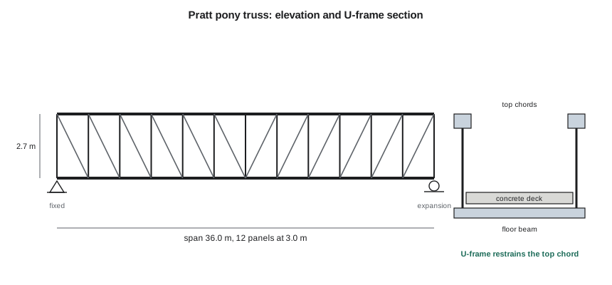
The trusses are prefabricated in weathering steel by a specialist supplier and delivered in two halves, which answers the client's question at the concept review about the narrow access road. The halves are bolted together at a midspan splice on temporary supports beside the north abutment, then lifted into place in one crane pick. The design is the team's; detailed design of the connections and the erection scheme would, in practice, be delegated to the supplier's engineer under a performance specification that the team writes, with the team reviewing the supplier's submittals.
Loads and the first sizing
The dead load is about 20 kN/m for the whole bridge: the 150 mm concrete deck on its form is the largest part at about 15 kN/m, then the trusses, floor beams, stringers and railings. The pedestrian load is 14.4 kN/m from lesson 2. With load factors of 1.20 on dead load and 1.70 on live load, the factored moment at midspan follows from the simply supported beam formula, and each truss resists half of it as a couple between its chords.
Here d is the depth between chord centroids. The chords are square hollow structural sections, the same size top and bottom for simple fabrication. The first trial uses a depth of span/15, a common starting point for pedestrian trusses.
Stiffness and frequency
For the deflection and frequency of a truss, the team treats it as an equivalent beam. The chords provide almost all the bending stiffness: two chords of area A at a distance d/2 from the neutral axis give each truss a second moment of area of about A d²/2, so the pair of trusses has I = A d². Web members add shear deformation that a beam model ignores; for a Pratt truss of these proportions it adds roughly 10 to 15 % to the deflection, and the team uses 12 %. The first vertical natural frequency of a simply supported beam with uniform mass m per unit length is
with the frequency reduced by the square root of 1.12 to reflect the extra flexibility. The mass is the dead load only; codes generally do not count pedestrians as mass for this purpose, because a light crowd changes the frequency little and a heavy one damps the motion.
# Pony truss superstructure: chord forces, deflection and vertical frequency for two truss depths
import math
UNITS = "SI"
SI = UNITS == "SI"
if SI:
    L, width = 36.0, 3.6                         # span and clear deck width (m)
    wD = 20.0                                    # dead load, kN/m (deck 15.2, floor 1.2, trusses 2.8, rails 0.8)
    wL = 4.0 * width                             # pedestrian load, kN/m
    gD, gL = 1.20, 1.70                          # load factors used in the design memo
    A = 11800e-6                                 # chord area, m2 (HSS 254 x 254 x 12.7)
    Fy, phi, E = 350e3, 0.90, 200e6              # kPa, -, kPa
    g = 9.81
else:
    L, width = 120.0, 12.0                       # ft
    wD = 1.37                                    # kip/ft
    wL = 90 * width / 1000                       # kip/ft
    gD, gL = 1.25, 1.75
    A = 17.2                                     # in2 (HSS 10 x 10 x 1/2)
    Fy, phi, E = 50.0, 0.95, 29000.0             # ksi, -, ksi
    g = 32.2
for d in ((2.4, 2.7) if SI else (8.0, 9.0)):
    M = (gD * wD + gL * wL) * L ** 2 / 8         # factored midspan moment, both trusses
    C = M / 2 / d                                # chord force per truss
    cap = phi * A * Fy                           # tension capacity of the bottom chord
    I = A * d ** 2                               # both trusses: 2 x (2 chords x A x (d/2)^2)
    if SI:
        EI = E * I                               # kN m2
        defl = 5 * wL * L ** 4 / (384 * EI) * 1.12 * 1000      # mm, +12 % for web shear deformation
        m = wD * 1000 / g                        # kg/m
        f1 = math.pi / (2 * L ** 2) * math.sqrt(EI * 1000 / m) / math.sqrt(1.12)
        unit_f, unit_d = "kN", "mm"
    else:
        EI = E * I                               # ksi x in2 x ft2 = kip ft2
        defl = 5 * wL * L ** 4 / (384 * EI) * 1.12 * 12        # in.
        m = wD / g                               # kip s2/ft2
        f1 = math.pi / (2 * L ** 2) * math.sqrt(EI / m) / math.sqrt(1.12)
        unit_f, unit_d = "kips", "in."
    print(f"Truss depth {d:g} {'m' if SI else 'ft'} (span/{L / d:.0f})")
    print(f"  factored chord force {C:,.0f} {unit_f}; bottom chord capacity {cap:,.0f} {unit_f}; ratio {C / cap:.2f}")
    print(f"  pedestrian load deflection {defl:.{0 if SI else 2}f} {unit_d} (limit {L / 360 * (1000 if SI else 12):.{0 if SI else 1}f})")
    print(f"  first vertical frequency {f1:.2f} Hz")
    if SI:
        if f1 < 3.0:
            amax = 0.25 * f1 ** 0.78
            G, alpha, zeta = 700.0, 0.4, 0.005               # walker weight (N), harmonic factor, damping
            Mmod = 0.5 * m * L                               # modal mass, kg
            ncyc = L / 0.75                                  # footsteps to cross the span
            a = alpha * G / (Mmod * 2 * zeta) * (1 - math.exp(-2 * math.pi * zeta * ncyc))
            print(f"  below 3 Hz: walker response about {a:.2f} m/s2 against a limit of {amax:.2f} m/s2"
                  f" -> {'OK' if a <= amax else 'not acceptable'}")
        else:
            print("  3 Hz or more: no acceleration check needed")
    else:
        W = wD * L
        fmin = 2.86 * math.log(180 / W)
        print(f"  weight W = {W:.0f} kips, 2.86 ln(180/W) = {fmin:.2f} Hz; 3.0 Hz criterion "
f"{'met' if f1 >= 3.0 else 'not met'}, weight criterion {'met' if f1 >= fmin else 'not met'}")Truss depth 2.4 m (span/15) factored chord force 1,636 kN; bottom chord capacity 3,717 kN; ratio 0.44 pedestrian load deflection 26 mm (limit 100) first vertical frequency 2.96 Hz below 3 Hz: walker response about 0.59 m/s2 against a limit of 0.58 m/s2 -> not acceptable Truss depth 2.7 m (span/13) factored chord force 1,454 kN; bottom chord capacity 3,717 kN; ratio 0.39 pedestrian load deflection 21 mm (limit 100) first vertical frequency 3.33 Hz 3 Hz or more: no acceleration check needed
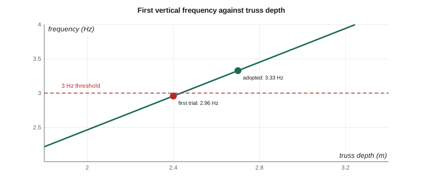
At a depth of 2.4 m the bridge is strong, with a chord force less than half the bottom chord's tension resistance, and stiff, with a pedestrian deflection of 26 mm against a limit of 100 mm. But its first vertical frequency is 2.96 Hz, just under the 3 Hz threshold, so S6 requires the acceleration check. The calculated response of a single walker in resonance, allowing for the number of steps it takes to cross the span, is about 0.59 m/s², just above the limit of 0.58 m/s². A bridge that fails by 2 % on a calculation with this much uncertainty in the damping is not a bridge the team wants to defend.
Increasing the depth to 2.7 m raises the frequency to 3.33 Hz, which needs no acceleration check, reduces the chord force and the deflection, and adds very little steel: the chords are the same size, and only the verticals and diagonals get longer. The team adopts 2.7 m, about span/13.
Worked problem
Why depth raises frequency so efficiently
If the chord area is unchanged and the depth goes from 2.4 m to 2.7 m, by how much does the frequency change, ignoring the small increase in mass?
Show solution
- \[I \propto d^2, \quad f_1 \propto \sqrt{I} \propto d\]
- \[\frac{f_{2.7}}{f_{2.4}} = \frac{2.7}{2.4} = 1.125\]
- \[2.96 \times 1.125 = 3.33\ \text{Hz}\]
Answer: Frequency rises in direct proportion to depth when the chords stay the same, which is why deepening the truss is cheaper than adding steel to the chords.
Strength checks
The bottom chord is in tension and has a large reserve. The top chord is in compression and is the critical strength member, because its buckling length depends on the U-frame stiffness. The team uses the approach in the steel design course: the top chord is treated as a compression member on an elastic foundation provided by the U-frames, with the U-frame stiffness calculated from the verticals and the floor beam acting as a portal. For the adopted proportions the effective buckling length works out at a little more than two panels, and the chord's factored resistance comfortably exceeds the factored force. The verticals are designed for the U-frame bending as well as their axial load, which is why they are larger than their axial forces alone would suggest.
The diagonals of a Pratt truss are in tension under symmetric load, but a crowd on half the span can reverse the force in the central diagonals. The team checks the half-span load case and finds a small compression in the two diagonals nearest midspan, which their sections easily carry. The floor beams are designed for the maintenance vehicle, which governs them, and the deck for local wheel loads. Connections are left to the supplier, with the forces tabulated on the drawings.
The deck is a one-way slab spanning between three lines of stringers at about 1.4 m centres, designed with the methods of the reinforced concrete course for the maintenance vehicle wheel loads, with the effects of the permanent steel form included. A broom finish gives grip for cyclists in wet weather, and a light camber of 25 mm is built into the trusses so that the deck does not sag below a straight line under its own weight, which would trap water at midspan and look wrong to users.
Weathering steel and durability
Weathering steel forms a dense, stable oxide layer that protects the steel underneath, so it needs no paint. It performs well when it dries out regularly and badly when it stays wet or is exposed to chlorides. Two details follow. The deck drains through scuppers that discharge clear of the steel, and the bottom chords and floor beam connections are detailed so that water cannot pond. And the city agrees to clear the deck by plowing and to use sand rather than salt on it, a condition written into the operations and maintenance manual. The railings are galvanized steel with a vertical-picket fence, 1.4 m high, tall enough for cyclists.
Practical points
- For long pedestrian spans, check frequency and liveliness before strength.
- Deepen the truss before adding steel to the chords; frequency rises in proportion to depth.
- Design the top chord of a pony truss with its U-frame restraint, and size the verticals for U-frame bending.
- Check half-span loading for reversal in the central diagonals.
- Detail weathering steel to drain and dry, and keep chlorides off it.
Common mistakes
MistakeAccepting a frequency just below the threshold because the acceleration check barely passes.
InsteadDamping is uncertain; a small change in depth buys a clear margin.
MistakeDesigning pony truss top chords with the panel length as the buckling length.
InsteadThe U-frame is an elastic restraint; calculate its stiffness and the resulting buckling length.
MistakeCounting pedestrians as mass in the frequency calculation.
InsteadUse the structural mass; a crowd changes the frequency little and adds damping.
MistakeSpecifying weathering steel without drainage details.
InsteadWet pockets and chlorides cause continuing corrosion; detail for drainage and drying.
Summary and key terms
- The bridge is a 36 m weathering steel Pratt pony truss with a concrete deck on floor beams and stringers.
- The chords give almost all the bending stiffness; shear deformation of the webs adds about 12 % to deflection.
- At 2.4 m depth the frequency was 2.96 Hz and the acceleration check failed by a small margin.
- At 2.7 m depth the frequency is 3.33 Hz, with chord force and deflection well within limits.
- The top chord is restrained by U-frames, and its buckling length follows from their stiffness.
- The trusses are delivered in two halves and lifted in one pick; connections are delegated to the supplier.
- Pratt truss
- A truss with vertical members in compression and diagonals in tension under gravity load.
- U-frame
- The frame formed by a floor beam and the two truss verticals it connects, restraining a pony truss top chord.
- Equivalent beam
- A beam with the bending stiffness of a truss, used for deflection and frequency estimates.
- Natural frequency
- A frequency at which a structure vibrates freely after being disturbed.
- Liveliness
- Perceptible vibration of a light structure under walking, running or jumping.
- Damping ratio
- The fraction of critical damping, a measure of how quickly vibration dies away.
- Weathering steel
- Low-alloy steel that forms a protective oxide layer and needs no paint where it can dry.
- Delegated design
- Design of a component by a supplier's engineer to a performance specification set by the designer.
Practice problems
Work each problem on paper first, then reveal the answer to check.
The factored load is 48.5 kN/m on a 36 m span. What is the factored chord force per truss at a 2.7 m depth?
Show answer
M = 48.5 × 36² / 8 = 7,857 kN·m; per truss 3,929 kN·m; C = 3,929 / 2.7 = 1,455 kN.
Why does a crowd on half the span matter for a Pratt truss?
Show answer
It can reverse the force in the central diagonals from tension to compression.
If the dead load rises by 8 %, how does the frequency change?
Show answer
It falls by a factor of 1/√1.08, about 3.8 %.
Why is salt kept off the deck?
Show answer
Chlorides prevent weathering steel from forming a stable protective layer and cause continuing corrosion.
Lesson quiz · 5 questions
Score 60% or more to complete this lesson.
Create a free account to save your progress, take quizzes and earn a certificate.