
CIV-341 · Lesson 5 of 12 · 18 min
Settlement of shallow foundations on sand
Footings on sand settle quickly. Because sand drains freely, most of the settlement happens as the load is applied, during construction, with a smaller creep component over the following years. The amounts are usually modest, but they are hard to predict: sand cannot be sampled without disturbing it, so its stiffness must be inferred from in-situ tests, and the methods that do so are empirical. This lesson presents three of the most widely used methods, applies them to the garage footing and to a footing on the deeper sand near the pump station, and shows how widely their predictions can differ.
Why sand settlement is difficult
The stiffness of sand depends on its density, its stress history, the stress level and the strain. A sand that has been preloaded by glacial ice or by an earlier structure is several times stiffer than the same sand in a normally consolidated state, but the SPT and CPT respond only modestly to that difference. Tube samples of sand lose their structure, so laboratory tests on them are of little use. As a result, settlement methods for sand are calibrated against field observations of real footings, and their accuracy is limited: Burland and Burbidge found that, even with good SPT data, the ratio of observed to predicted settlement ranged over a factor of about two either way.
The good news is that the settlements involved are small, typically 10 to 25 mm for footings designed by bearing capacity with a factor of safety of 3, and that most of the settlement occurs before the finishes are installed. For footings on sand, the main purpose of a settlement calculation is often to set a bearing pressure that keeps the settlement below 25 mm, the traditional limit associated with Terzaghi and Peck's design charts.
Elastic solutions
Elastic theory gives the settlement of a footing on a uniform, linearly elastic half-space with modulus \(E_s\) and Poisson's ratio \(\nu\):
where \(q\) is the net pressure and \(I_s\) is an influence factor that depends on the shape and rigidity of the footing and the thickness of the compressible layer, about 0.95 at the centre of a flexible square and 0.82 for a rigid square on a deep layer. The difficulty lies not in the formula but in choosing \(E_s\), which for sand increases with depth and decreases with strain. Correlations such as \(E_s \approx 2.5\) to \(3.5\,q_c\) from the CPT are approximate, and the elastic formula is best used with a modulus that varies with depth, which leads to Schmertmann's method.
Schmertmann's strain influence method
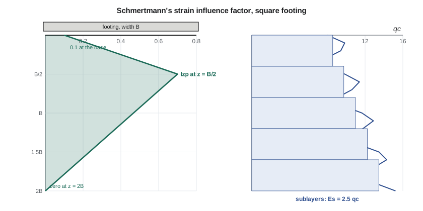
In 1970, and in an improved form with Hartman and Brown in 1978, John Schmertmann proposed a method based on the observation that the vertical strain beneath a footing on sand is greatest not at the base but at a depth of about half the footing width, and becomes negligible at a depth of about twice the width for a square footing or four times for a strip. He represented the distribution by a triangular strain influence factor \(I_z\). For a square footing, \(I_z\) rises from 0.1 at the base to a peak value \(I_{zp}\) at \(z = B/2\) and falls to zero at \(z = 2B\). The peak value increases with the ratio of the net pressure to the effective stress at the depth of the peak:
The settlement is the sum over sublayers of the strain influence factor divided by the modulus, multiplied by the net pressure and two correction factors:
where \(\sigma'_0\) is the effective stress at the founding level, \(C_1\) accounts for the embedment of the footing and \(C_2\) for creep with time \(t\) in years. The modulus for an axisymmetric (square) footing is taken as \(E_s = 2.5q_c\), and for a strip as \(3.5q_c\). Because the method uses the CPT profile directly, it captures layering and the increase of stiffness with depth.
The Burland and Burbidge method
Burland and Burbidge analysed more than 200 case records of footings, rafts and embankments on sand and gravel and in 1985 published a method based on the SPT. For a normally consolidated sand, the settlement in millimetres at the end of construction is
where \(q'\) is the gross effective bearing pressure in kPa, \(B\) is in metres and \(\bar N\) is the average measured SPT blow count over the depth of influence \(z_I \approx B^{0.763}\). For a sand that has been preloaded, the settlement is about one third as much. Correction factors adjust for the shape of the footing, for a sand layer thinner than \(z_I\) and for time, with a creep factor \(f_t = 1 + R_3 + R\log_{10}(t/3)\), typically \(R_3 = 0.3\) and \(R = 0.2\) for static loads. The method is attractive because it gives both a best estimate and a probable range, and because it uses SPT data, which are available on most sites.
Terzaghi and Peck, and plate tests
The oldest method in common use, Terzaghi and Peck's chart of 1948, gives the bearing pressure that causes 25 mm of settlement as a function of footing width and SPT blow count. It is known to be conservative, often by a factor of two or more, and Meyerhof and others later proposed less conservative versions. Plate load tests, in which a steel plate 300 to 760 mm across is loaded in a pit, measure the settlement directly, but only for the shallow soil beneath the small plate; scaling the result to a full-size footing is unreliable when the soil changes with depth.
Worked problem
Schmertmann at the garage footing
The garage footing applies a net pressure of 215 kPa. The sand extends only 2.0 m below the base; the CPT gives \(q_c\) rising from 9 MPa at the base. Find \(I_{zp}\), \(C_1\) and \(C_2\) for 25 years.
Show solution
- The peak is at \(z = B/2 = 1.5\) m below the base, 3.5 m below grade, where \(\sigma'_{vp} = 18.0(2.5) + 9.99(1.0) = 55.0\) kPa:
- \[I_{zp} = 0.5 + 0.1\sqrt{\frac{215}{55.0}} = 0.698\]
- Embedment and creep corrections, with \(\sigma'_0 = 36\) kPa:
- \[C_1 = 1 - 0.5\frac{36}{215} = 0.92 \qquad C_2 = 1 + 0.2\log_{10}\frac{25}{0.1} = 1.48\]
- The script integrates \(I_z/E_s\) over the 2.0 m of sand and gives 9.5 mm.
Answer: The calculation covers only the sand. The strain influence diagram extends to 2B, deep into the clay, but the clay is not a sand; its compression is calculated by consolidation theory in lesson 6 and added.
Sofia's script applies Schmertmann's method to the garage footing and to a 2.0 m footing for the salt shed near BH-4, where the sand is 7.0 m thick, and compares both with the Burland and Burbidge method.
# Settlement of footings on the sand: Schmertmann (1978) and Burland and Burbidge (1985)
from math import sqrt, log10
def schmertmann(B, Df, dp, s0, sv_eff, qc_at, zmax_soil, t_years=25.0, label=''):
    """Square footing; returns settlement (mm) of the sand above zmax_soil (depth below the base)."""
    zp = B / 2; Izp = 0.5 + 0.1 * sqrt(dp / sv_eff(Df + zp))
    def Iz(z):
        return 0.1 + (Izp - 0.1) * z / zp if z <= zp else max(0.0, Izp * (2 * B - z) / (1.5 * B))
    C1 = max(0.5, 1 - 0.5 * s0 / dp); C2 = 1 + 0.2 * log10(t_years / 0.1)
    n, total = 40, 0.0
    zend = min(2 * B, zmax_soil); dz = zend / n
    for k in range(n):
        z = (k + 0.5) * dz
        Es = 2.5 * qc_at(Df + z)               # square footing, Es = 2.5 qc
        total += Iz(z) / Es * dz
    s = C1 * C2 * dp * total * 1000
    print(f"{label}: Izp = {Izp:.3f}, C1 = {C1:.2f}, C2 = {C2:.2f}, depth used {zend:.1f} m of {2*B:.1f} m -> {s:.1f} mm")
    return s
def sv_eff(z):
    s = 18.0 * min(z, 2.5) + 19.8 * max(0.0, z - 2.5)
    return s - 9.81 * max(0.0, z - 2.5)

# interior garage footing: 3.0 m at 2.0 m, net 215 kPa; sand only 2.0 m thick below the base
qc_bh2 = lambda z: 9000 + 2000 * (z - 2.0)      # CPT tip resistance in the sand (kPa)
s1 = schmertmann(3.0, 2.0, 215.0, 36.0, sv_eff, qc_bh2, 2.0, label='Garage footing, sand above the clay')
# a 2.0 m footing near BH-4, where the sand extends to 7.0 m: net 200 kPa at 1.5 m
qc_bh4 = lambda z: 8000 + 1300 * (z - 1.5)
s2 = schmertmann(2.0, 1.5, 200.0, 27.0, sv_eff, qc_bh4, 5.5, label='Salt shed footing near BH-4  ')

# Burland and Burbidge: normally consolidated sand, s = q' B^0.7 Ic, Ic = 1.71 / N^1.4
def burland(B, q_eff, Nbar, Hs=None):
    zI = B ** 0.763; Ic = 1.71 / Nbar ** 1.4
    fl = 1.0 if Hs is None or Hs >= zI else (Hs / zI) * (2 - Hs / zI)
    ft = 1 + 0.3 + 0.2 * log10(25 / 3)          # 25 years, static load
    return q_eff * B ** 0.7 * Ic * fl, q_eff * B ** 0.7 * Ic * fl * ft, zI
for lab, B, q, N, Hs in (('Garage footing', 3.0, 251.0, 14, 2.0), ('Salt shed footing', 2.0, 227.0, 15, 5.5)):
    s, st, zI = burland(B, q, N, Hs)
print(f"Burland and Burbidge, {lab}: zI = {zI:.2f} m, end of construction {s:.1f} mm, 25 years {st:.1f} mm")Garage footing, sand above the clay: Izp = 0.698, C1 = 0.92, C2 = 1.48, depth used 2.0 m of 6.0 m -> 9.5 mm Salt shed footing near BH-4 : Izp = 0.711, C1 = 0.93, C2 = 1.48, depth used 4.0 m of 4.0 m -> 16.3 mm Burland and Burbidge, Garage footing: zI = 2.31 m, end of construction 22.6 mm, 25 years 33.5 mm Burland and Burbidge, Salt shed footing: zI = 1.70 m, end of construction 14.2 mm, 25 years 21.1 mm
Reading the results
Schmertmann's method gives 9.5 mm in the 2 m of sand under the garage footing and 16 mm for the salt shed footing, where the whole strain influence zone lies in the sand. Burland and Burbidge give 23 mm and 14 mm at the end of construction, rising to 34 and 21 mm after 25 years. For the salt shed, the two methods agree reasonably; for the garage footing, they differ by more than a factor of two, partly because Burland and Burbidge use the gross pressure and an average blow count while Schmertmann uses the net pressure and the CPT profile. Neither result is alarming, and Dr. Kowalczyk adopts 10 to 20 mm for the immediate settlement of the garage footings in the sand, most of which will occur as the structure is built.
The comparison illustrates a general truth about settlement on sand. The methods do not agree closely with each other or with reality, and the engineer should not report a settlement to the nearest millimetre. A range, an understanding of which method suits the data available, and a design that tolerates the upper end of the range are worth more than precision.
Allowable bearing pressure for settlement
Because settlement increases roughly in proportion to the pressure, a settlement calculation can be inverted to give the pressure that causes a target settlement, usually 25 mm. That pressure, with the serviceability resistance factor applied, is the serviceability bearing resistance that the geotechnical report gives to the structural engineer, alongside the factored ultimate bearing resistance. For wide footings on sand, the serviceability value is usually lower and governs; for narrow footings, the ultimate value often governs. Many reports present both as a function of footing width.
Other causes of settlement in sand
Static loads are not the only source of settlement in sand. Vibrations from machinery, pile driving or traffic can densify loose sands and cause settlements much larger than those under static load. A rising and falling water table causes small settlements in loose sands as the grains rearrange. Earthquake shaking can cause liquefaction of loose saturated sands, with large settlements and loss of bearing; Thunder Bay lies in a region of low seismic hazard, but the check is required for sites of higher hazard. And sands with a cemented or collapsible structure, such as some wind-deposited soils, can collapse suddenly when wetted.
Practical points
- Use the net pressure in Schmertmann's method and the gross effective pressure in Burland and Burbidge.
- Integrate over the full depth of influence, but calculate the compression of any clay layer within it by consolidation theory.
- Report settlement on sand as a range and design the structure to tolerate the upper end.
- Remember that most settlement on sand occurs during construction.
- Consider vibration, water table changes and seismic effects for loose sands.
Common mistakes
MistakeReporting a sand settlement to the nearest millimetre.
InsteadGive a range; the methods are approximate.
MistakeApplying Schmertmann's method through a clay layer.
InsteadStop the sand calculation at the clay and use consolidation theory for the clay.
MistakeUsing corrected \((N_1)_{60}\) values in Burland and Burbidge.
InsteadThe method was calibrated with measured blow counts.
MistakeExtrapolating a small plate load test to a large footing on layered ground.
InsteadThe plate stresses only shallow soil; use methods that account for the full depth of influence.
Summary and key terms
- Settlement of sand is mostly immediate, small and hard to predict closely.
- Elastic: \(s = qB(1 - \nu^2)I_s/E_s\); the difficulty is choosing \(E_s\).
- Schmertmann: \(s = C_1C_2\Delta p\sum(I_z/E_s)\Delta z\), with \(I_z\) peaking at \(B/2\) and \(E_s = 2.5q_c\) for square footings.
- Burland and Burbidge: \(s = q'B^{0.7}\,1.71/\bar N^{1.4}\) mm for normally consolidated sand, one third of that for preloaded sand.
- Garage footing: about 10 to 20 mm in the sand, to be added to the consolidation of the clay.
- Immediate settlement
- Settlement that occurs as the load is applied, without significant change in water content.
- Strain influence factor
- A dimensionless factor describing how vertical strain varies with depth beneath a footing.
- Creep factor
- A correction for the slow increase of settlement with time under constant load.
- Embedment correction
- Schmertmann's factor C1 for the reduction in settlement due to the overburden at the founding level.
- Depth of influence
- The depth below a footing within which significant compression occurs.
- Preloaded sand
- Sand that has carried a higher stress in the past and is therefore stiffer.
- Plate load test
- A field test loading a small steel plate to measure the load-settlement response of the soil.
- Liquefaction
- Loss of strength of loose saturated sand due to pore pressure build-up during shaking.
Practice problems
Work each problem on paper first, then reveal the answer to check.
A 2.0 m square footing applies a net pressure of 180 kPa. The effective stress at 1.0 m below its base is 40 kPa. Find \(I_{zp}\).
Show answer
\(0.5 + 0.1\sqrt{4.5} = 0.71\).
Find \(C_2\) for 50 years.
Show answer
\(1 + 0.2\log_{10}(500) = 1.54\).
By Burland and Burbidge, estimate the settlement of a 2.5 m footing on normally consolidated sand with \(\bar N = 20\) and \(q' = 200\) kPa.
Show answer
\(I_c = 1.71/20^{1.4} = 0.0258\); \(s = 200(2.5^{0.7})(0.0258) = 9.8\) mm.
Why is Schmertmann's peak strain at a depth of about B/2 rather than at the footing base?
Show answer
Near the base the soil is confined by the footing and the vertical stress increase has not yet spread; the combination of stress increase and low confinement produces the largest strain at about B/2.
Lesson quiz · 5 questions
Score 60% or more to complete this lesson.
Create a free account to save your progress, take quizzes and earn a certificate.