
CIV-341 · Lesson 2 of 12 · 21 min
Site investigation for foundation design
CIV-340 described how boreholes, samples and in-situ tests reveal the ground. This lesson looks at the same investigation through the eyes of the foundation designer. The questions are more specific: how deep must the boreholes go to see every layer the foundations will stress, how many are needed, which tests give the parameters that the bearing, settlement and pile calculations require, and how should the results be turned into design values? The lesson reinterprets the Kestrel Bay boreholes for the garage footings and plans the extra investigation needed for the new fleet storage building.
What the foundation designer needs
Each design method in this course needs particular information. Bearing capacity on sand needs the friction angle and the unit weight; on clay it needs the undrained shear strength. Settlement on sand needs the stiffness, usually from the CPT or SPT; settlement on clay needs the compression indices, the preconsolidation stress and the coefficient of consolidation from oedometer tests. Pile design needs the strength or the effective stress profile along the whole pile length and the resistance of the bearing layer at the toe, plus anything that will make driving or drilling difficult: boulders, cemented layers, artesian water or rock. Every design also needs the groundwater levels and how they change through the seasons.
An investigation should therefore be planned around the foundations being considered, not simply copied from the last job. When the foundation type is not yet known, as is common, the investigation must be deep enough and varied enough to support both a shallow and a deep option, and it is often done in stages: a preliminary investigation to establish the ground model, and a design investigation focused on the chosen foundations.
Depth of investigation
Boreholes must extend below every layer that will be stressed significantly by the foundations, or that could affect their stability. Several rules of thumb exist.
- For isolated spread footings, at least one and a half to two times the footing width below the founding level, and deeper where footings are closely spaced.
- For a building on footings or a mat, a common criterion is the depth at which the stress increase from the building falls to about 10 % of the effective overburden stress, which for wide buildings on soft soils may be one to two times the building width.
- For piles, at least about 3 m, or five pile diameters, below the expected toe level, and deeper for pile groups, so that the soil stressed by the group is known.
- Wherever possible, boreholes should prove a competent stratum, such as dense till or rock, for a reasonable thickness, so that a soft layer beneath it is not missed. Rock should be cored for at least about 3 m to distinguish bedrock from a boulder.
The 10 % criterion is a useful check because it adapts to the soil. Under a footing on soft ground, the effective overburden stress is low and the stress increase must fall a long way before it becomes negligible; under a footing on dense soil, the investigation can stop sooner.
Number and spacing of boreholes
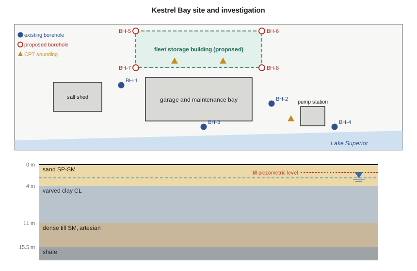
There is no exact rule for the number of boreholes. For buildings, spacings of about 15 to 30 m on uniform ground and closer on variable ground are typical, with at least three boreholes for any significant structure so that the dip of layers can be seen. Variability is the controlling factor: on glacial ground, where till surfaces and lenses of sand or silt change over short distances, more holes are needed than on a uniform lake clay. CPT soundings between boreholes are an economical way to fill gaps, because they give a continuous profile in minutes and can be correlated with the nearby borehole logs.
In-situ tests for foundation design
The standard penetration test (SPT) remains the most widely used test in North American practice, mainly because it recovers a disturbed sample at every test depth. For foundation design its blow count must be corrected. The hammer energy correction gives \(N_{60}\), the blow count at 60 % of the theoretical free-fall energy:
where \(E_r\) is the measured energy ratio of the hammer in percent. Automatic trip hammers typically deliver about 70 to 90 %, safety hammers about 55 to 65 %. The overburden correction then normalizes the blow count to an effective stress of one atmosphere, giving \((N_1)_{60}\):
Smaller corrections for rod length, borehole diameter and sampler type are sometimes applied. The normalized blow count correlates with relative density and friction angle. Two widely used relations, both approximate, are Skempton's relative density relation for normally consolidated sands and a fit to the chart of Peck, Hanson and Thornburn:
The cone penetration test (CPT) gives a continuous record of tip resistance \(q_c\) (corrected to \(q_t\) for pore pressure acting on the cone), sleeve friction and, with a piezocone, pore pressure. In clays the undrained shear strength follows from the net tip resistance and an empirical cone factor:
with \(N_{kt}\) typically between about 10 and 20, best calibrated against field vane or laboratory tests on the same site. In sands, the tip resistance gives the stiffness used in the settlement methods of lesson 5. Other in-situ tests useful for foundations include the field vane for soft clays, the pressuremeter, which measures the stress-strain response of the ground in a borehole and is well suited to settlement and lateral pile analyses, the flat dilatometer, and geophysical methods such as seismic shear wave velocity profiling, which gives the small-strain stiffness and the site class for seismic design.
Groundwater
Groundwater controls effective stress, and therefore bearing resistance, settlement and pile shaft resistance. It also controls construction: excavations below the water table in sand need dewatering, and artesian pressures can lift the base of an excavation. Water levels measured in open boreholes at the end of drilling are often misleading, especially in clays where the water takes days or weeks to reach equilibrium. Standpipe or vibrating wire piezometers sealed into each aquifer give reliable levels, and readings over at least one spring thaw show the seasonal high. At Kestrel Bay, the vibrating wire piezometer in the till was what revealed the artesian pressure that dominated the pump station design in CIV-340.
From test results to design values
Test results scatter. A profile of SPT blow counts in a uniform sand might vary by a factor of two from one test to the next. The engineer must choose a value for design that is representative of the soil mass that controls the behaviour of the foundation. That value, often called the characteristic value, is a cautious estimate of the average over the zone of influence, not the lowest single result and not the mean. A footing averages the soil over a volume of several cubic metres, so a single low blow count matters less than a consistent trend; a pile toe resting on a small zone is more sensitive to local variations. Where a parameter controls the design and the data are scattered, it is better to carry out more tests than to argue about a value.
Worked problem
Interpreting the SPT in the sand
At 2.25 m in BH-2, \(N = 15\) with an automatic hammer of 80 % energy ratio. Find \(N_{60}\), \((N_1)_{60}\), the relative density and the friction angle.
Show solution
- Energy correction:
- \[N_{60} = 15\Big(\frac{80}{60}\Big) = 20.0\]
- The water table is at 2.5 m, so \(\sigma'_v = 18.0(2.25) = 40.5\) kPa:
- \[C_N = \Big(\frac{100}{40.5}\Big)^{0.5} = 1.57 \qquad (N_1)_{60} = 1.57(20.0) = 31.4\]
- \[D_r \approx \sqrt{\frac{31.4}{60}} = 0.72 \qquad \phi' \approx 27.1 + 0.3(31.4) - 0.00054(31.4)^2 = 36.0^\circ\]
Answer: This is one of the higher values in the profile. Averaged over the sand, the SPT gives a friction angle of about 35°, and Dr. Kowalczyk adopts 34° for design, consistent with the laboratory tests of CIV-340.
Sofia's script interprets the whole SPT profile in the sand, the CPT soundings in the clay, and checks the depth of investigation for the garage footing using the 10 % stress criterion.
# BH-2 interpretation for foundation design: SPT in the sand, CPT in the clay, investigation depth
from math import sqrt, atan, degrees
pa, ER = 100.0, 80.0                              # atmospheric pressure (kPa), hammer energy ratio (%)
def sv(z):                                         # total and effective vertical stress in the sand (kPa)
    s = 18.0 * min(z, 2.5) + 19.8 * max(0.0, z - 2.5)
    return s, s - 9.81 * max(0.0, z - 2.5)
spt = [(0.75, 9), (1.5, 12), (2.25, 15), (3.0, 14), (3.75, 18)]
print(" z(m)   N   N60  s'v   CN  (N1)60  Dr(%)  phi'(deg)")
phis = []
for z, N in spt:
    N60 = N * ER / 60; s, se = sv(z)
    CN = min(1.7, sqrt(pa / se)); N160 = CN * N60
    Dr = 100 * sqrt(N160 / 60)                     # Skempton: (N1)60 = 60 Dr^2 (normally consolidated)
    phi = 27.1 + 0.3 * N160 - 0.00054 * N160**2    # Peck, Hanson and Thornburn chart (Wolff fit)
    phis.append(phi)
    print(f"{z:5.2f} {N:3d} {N60:5.1f} {se:5.1f} {CN:5.2f} {N160:6.1f} {Dr:6.0f} {phi:8.1f}")
print(f"Mean phi' from SPT = {sum(phis)/len(phis):.1f} deg; design value adopted 34 deg")

print("\nCPT in the clay: su = (qt - sigma_v) / Nkt")
for z, qt in [(5.0, 1000), (7.0, 1130), (9.0, 1150), (10.5, 1220)]:
    s = 18.0 * 2.5 + 19.8 * 1.5 + 18.0 * (z - 4.0)
    print(f"z = {z:4.1f} m  qt = {qt} kPa  su(Nkt = 15) = {(qt - s)/15:4.0f}  su(Nkt = 17) = {(qt - s)/17:4.0f} kPa")

print("\nDepth of investigation: Boussinesq stress under the centre of the footing vs 10 % of s'v")
from math import pi, atan2
def corner(m, n):
    s = m*m + n*n + 1
    return (2*m*n*sqrt(s)/(s + m*m*n*n)*(s + 1)/s + atan2(2*m*n*sqrt(s), s - m*m*n*n)) / (4*pi)
def sv_eff(z):
    if z <= 4.0: return sv(z)[1]
    if z <= 11.0:
        s = 18.0*2.5 + 19.8*1.5 + 18.0*(z - 4.0); u = 14.7 + (93.2 - 14.7)*(z - 4.0)/7.0
    else:                                        # artesian till, piezometric level 1.5 m below grade
        s = 18.0*2.5 + 19.8*1.5 + 18.0*7.0 + 21.5*(z - 11.0); u = 9.81*(z - 1.5)
    return s - u
B, q, Df = 3.0, 215.0, 2.0
for z in (3.0, 5.0, 7.0, 9.0, 11.0, 12.0, 13.0):
    ds = 4 * q * corner(B/2/(z - Df), B/2/(z - Df))
print(f"z = {z:4.1f} m d_sigma = {ds:5.1f} kPa 0.1 s'v = {0.1*sv_eff(z):4.1f} kPa {'continue' if ds > 0.1*sv_eff(z) else 'stop'}")z(m) N N60 s'v CN (N1)60 Dr(%) phi'(deg) 0.75 9 12.0 13.5 1.70 20.4 58 33.0 1.50 12 16.0 27.0 1.70 27.2 67 34.9 2.25 15 20.0 40.5 1.57 31.4 72 36.0 3.00 14 18.7 50.0 1.41 26.4 66 34.6 3.75 18 24.0 57.5 1.32 31.7 73 36.1 Mean phi' from SPT = 34.9 deg; design value adopted 34 deg CPT in the clay: su = (qt - sigma_v) / Nkt z = 5.0 m qt = 1000 kPa su(Nkt = 15) = 60 su(Nkt = 17) = 53 kPa z = 7.0 m qt = 1130 kPa su(Nkt = 15) = 67 su(Nkt = 17) = 59 kPa z = 9.0 m qt = 1150 kPa su(Nkt = 15) = 66 su(Nkt = 17) = 58 kPa z = 10.5 m qt = 1220 kPa su(Nkt = 15) = 69 su(Nkt = 17) = 60 kPa Depth of investigation: Boussinesq stress under the centre of the footing vs 10 % of s'v z = 3.0 m d_sigma = 185.5 kPa 0.1 s'v = 5.0 kPa continue z = 5.0 m d_sigma = 72.3 kPa 0.1 s'v = 6.7 kPa continue z = 7.0 m d_sigma = 32.1 kPa 0.1 s'v = 8.0 kPa continue z = 9.0 m d_sigma = 17.5 kPa 0.1 s'v = 9.4 kPa continue z = 11.0 m d_sigma = 10.9 kPa 0.1 s'v = 10.8 kPa continue z = 12.0 m d_sigma = 8.9 kPa 0.1 s'v = 11.9 kPa stop z = 13.0 m d_sigma = 7.4 kPa 0.1 s'v = 13.1 kPa stop
Reading the results
The normalized blow counts in the sand range from 20 to 32, relative densities from 58 to 73 % and friction angles from 33 to 36°, an average of 34.9°. The CPT gives an undrained strength of 60 to 69 kPa with \(N_{kt} = 15\) and 53 to 60 kPa with \(N_{kt} = 17\), the factor that brought the CPT into agreement with the field vane in CIV-340. The design value of 55 kPa sits at the lower end of that range. The stress check shows that the stress increase under the footing stays above 10 % of the effective overburden stress down to about 11 m, the base of the clay: because the clay has low effective stress, the footing stresses it significantly through its whole thickness. Boreholes for footings on this site must reach the till, more than three footing widths below the founding level, and the 1.5B rule of thumb would have stopped well short.
Planning the fleet building investigation
The fleet storage building will stand about 60 m north of the garage, where only BH-1 is close. Its column loads are larger and, as lesson 8 will show, it will almost certainly need piles to the till. Dr. Kowalczyk specifies four more boreholes, BH-5 to BH-8, at the corners of the footprint, each continued through the till and cored 3 m into the shale, with SPT at 0.75 m intervals in the sand and 1.5 m intervals below, thin-walled tube samples of the clay for oedometer and triaxial tests, and a vibrating wire piezometer in the till in two of the holes. Two CPT soundings in the middle of the footprint will be pushed to refusal in the till, with pore pressure dissipation tests in the clay to measure the coefficient of consolidation. She also asks for the driller to record carefully any boulders or cobbles in the till, because they matter for pile driving.
Owen asks why the till needs such attention when it is so dense. The answer is that the till will be the bearing layer for the piles. Its thickness above the rock, its density, the presence of boulders and its pore pressure will decide the pile type, the toe level and the driving criteria. Most pile problems on glacial sites come from layers that were not seen in the investigation: a boulder field, a soft layer below the till, or a rock surface that dips steeply between boreholes.
Practical points
- Plan the investigation around the foundations being considered, and stage it if the foundation type is not known.
- Take boreholes through all layers stressed by the foundations; use the 10 % criterion to check the depth.
- Correct SPT blow counts for hammer energy and overburden before using correlations.
- Calibrate the CPT cone factor against vane or laboratory tests on the same site.
- Install sealed piezometers in each aquifer and read them through a spring thaw.
- Choose characteristic values as cautious estimates of the average over the zone of influence.
Common mistakes
MistakeStopping boreholes at a fixed depth, such as 6 m, regardless of the foundations.
InsteadRelate the depth to the stressed zone, and prove a competent layer.
MistakeUsing raw SPT blow counts in correlations.
InsteadCorrect for energy and overburden first.
MistakeTaking the water level in an open borehole at the end of drilling as the groundwater level.
InsteadUse sealed piezometers and read them over time.
MistakeDesigning on the single lowest test value.
InsteadUse a cautious average over the zone that controls the behaviour, and investigate further if scatter matters.
Summary and key terms
- Each design method needs particular parameters; plan the investigation to provide them.
- Investigate below the stressed zone: about 1.5 to 2B for footings, the 10 % stress criterion for buildings, at least 3 m or 5 diameters below pile toes.
- \(N_{60} = N E_r/60\); \((N_1)_{60} = C_N N_{60}\) with \(C_N = (p_a/\sigma'_v)^{0.5} \le 1.7\).
- CPT: \(s_u = (q_t - \sigma_v)/N_{kt}\), with \(N_{kt}\) calibrated on site.
- At Kestrel Bay the sand has \(\phi' \approx 34^\circ\) and the clay \(s_u = 55\) kPa; footings stress the clay to its base, so boreholes must reach the till.
- Desk study
- A review of existing information about a site before field work.
- Energy ratio
- The energy delivered by an SPT hammer as a percentage of the theoretical free-fall energy.
- (N1)60
- The SPT blow count corrected to 60 % energy and to an effective overburden stress of one atmosphere.
- Cone factor Nkt
- The empirical factor relating the net cone tip resistance to the undrained shear strength.
- Characteristic value
- A cautious estimate of a soil parameter representative of the soil mass that governs the behaviour.
- Piezometer
- An instrument sealed into a soil layer to measure its pore water pressure.
- Pressuremeter
- An in-situ test that expands a probe in a borehole to measure the stress-strain response of the ground.
- Zone of influence
- The volume of ground significantly stressed by a foundation.
Practice problems
Work each problem on paper first, then reveal the answer to check.
An SPT at 3.0 m gives \(N = 10\) with a safety hammer of 60 % energy ratio. The effective stress is 45 kPa. Find \((N_1)_{60}\).
Show answer
\(N_{60} = 10\); \(C_N = (100/45)^{0.5} = 1.49\); \((N_1)_{60} = 14.9\).
A CPT in clay gives \(q_t = 900\) kPa where \(\sigma_v = 110\) kPa. Find \(s_u\) with \(N_{kt} = 14\).
Show answer
\((900 - 110)/14 = 56\) kPa.
Why is the depth of investigation beneath a footing on soft clay greater than the 1.5B rule suggests?
Show answer
The low effective stress in the clay means the stress increase remains significant relative to it to a greater depth.
Give two reasons for coring at least 3 m into rock at a pile site.
Show answer
To distinguish bedrock from a boulder and to measure the rock quality and strength at the pile toe.
Lesson quiz · 5 questions
Score 60% or more to complete this lesson.
Create a free account to save your progress, take quizzes and earn a certificate.