
CHE-380 · Lesson 8 of 12 · 22 min
Relief systems: scenarios, devices and codes
Every pressure vessel can be overpressured: a control valve fails open, cooling is lost, an outlet is blocked, a fire engulfs the vessel, or a reaction runs away. When the pressure rises past what the vessel was designed to hold, it may rupture, releasing its contents and a blast. Relief devices are the last engineered line of defence against that outcome. They open automatically at a set pressure and release enough material to keep the pressure within limits. In the layers of protection described in CHE-374, relief devices sit outside the control system, alarms and safety instrumented systems; they work when everything else has failed. This lesson covers how relief requirements are identified, which devices are used and what the codes require. Lesson 9 covers sizing.
The relief design sequence
Relief design follows a standard sequence. First, list the equipment that needs protection and its design pressure. Second, identify every credible overpressure scenario for each item. Third, calculate the required relief rate for each scenario. Fourth, choose the governing scenario, the one that needs the largest relief capacity. Fifth, select the device type and size it. Sixth, design the inlet and outlet piping and the disposal system that receives the discharge. Finally, document everything so that the design can be checked and kept up to date when the process changes. Many incidents have involved relief systems that were adequate when designed but were never revisited after a change in throughput, feed or equipment.
At Kingfisher Bioenergy, Theo works through the sequence for V-410, the new ester rundown drum that receives product from the ester column before it goes to storage. Its maximum allowable working pressure, MAWP, is 350 kPa gauge. Nadia insists that he start with the scenario list rather than the sizing equations, because a perfectly sized valve for the wrong scenario protects nothing.
Codes and responsibilities
Pressure vessels are designed and built to CSA B51 and the TSSA pressure equipment rules, which adopt the ASME Boiler and Pressure Vessel Code. The code requires overpressure protection for every pressure vessel and sets the limits on how far pressure may rise during relief. The scenarios and the sizing of relief devices and disposal systems are covered by the American Petroleum Institute's standards: API Standard 520 for sizing, selection and installation, and API Standard 521 for pressure-relieving and depressuring systems, which describes the causes of overpressure and the design of flares and other disposal systems. Atmospheric and low-pressure storage tanks, such as the ethyl acetate tanks T-401 to T-403, are protected by vents designed to API Standard 2000, which covers normal breathing during filling and emptying and emergency venting for fire exposure.
Identifying relief scenarios
API 521 lists the common causes of overpressure, and most companies use it as a checklist. Each item is considered for each vessel, and those that are credible are analysed. The main categories are blocked outlets, where a pump or compressor continues to feed a vessel whose outlet has been closed; utility failures, such as loss of cooling water, power, instrument air or steam; control valve failures, where a valve fails fully open and admits more flow or heat than normal; heat exchanger tube rupture, where high-pressure fluid enters the low-pressure side; external fire, which heats the vessel and boils its contents; chemical reactions, including runaways such as the one examined for the pre-reactor in CHE-345; and thermal expansion of liquid trapped between closed valves.
For each scenario the engineer asks how the pressure rises and what flows through the relief device. A blocked outlet on a liquid-full vessel needs relief of the full pump flow as liquid. A cooling failure on a condenser needs relief of the vapour that is no longer condensed. A fire boils the liquid and needs relief of the vapour generated. A runaway reaction may produce a two-phase mixture of foam and gas that is much harder to relieve. The relief rate depends on what fails and what keeps running, and the analysis must say which assumptions it makes about operator action; most practice does not credit operator response for relief sizing.
# Relief scenarios for V-410, the ester rundown drum (MAWP 350 kPa gauge): which case governs?
cases = (("blocked outlet on transfer pump (liquid)", 18.0), ("cooling water failure on reflux condenser", 2.6),
         ("external pool fire (wetted area)", 9.4), ("steam control valve fails open on reboiler", 6.1),
         ("nitrogen regulator fails open", 1.1))   # required relief rate t/h for each credible case, illustrative
for name, w in sorted(cases, key=lambda c: -c[1]): print(f"{w:6.1f} t/h  {name}")
gov = max(cases, key=lambda c: c[1])
print(f"largest mass rate: {gov[0]}; the governing case is the one needing the largest orifice area (lesson 9)")
# Set pressure and accumulation (ASME Section VIII style limits)
MAWP = 350.0   # kPa(g)
for name, acc in (("single valve, non-fire", 0.10), ("multiple valves, non-fire", 0.16), ("fire case", 0.21)):
print(f"{name}: maximum relieving pressure {MAWP * (1 + acc):.0f} kPa(g)")18.0 t/h blocked outlet on transfer pump (liquid) 9.4 t/h external pool fire (wetted area) 6.1 t/h steam control valve fails open on reboiler 2.6 t/h cooling water failure on reflux condenser 1.1 t/h nitrogen regulator fails open largest mass rate: blocked outlet on transfer pump (liquid); the governing case is the one needing the largest orifice area (lesson 9) single valve, non-fire: maximum relieving pressure 385 kPa(g) multiple valves, non-fire: maximum relieving pressure 406 kPa(g) fire case: maximum relieving pressure 424 kPa(g)
For V-410, five scenarios survive the screening. The largest mass rate is the blocked outlet of the transfer pump, 18 t/h of liquid. The external fire gives 9.4 t/h of vapour, the reboiler steam valve failing open 6.1 t/h, the condenser cooling failure 2.6 t/h, and a failed-open nitrogen regulator 1.1 t/h. But mass rate is not the whole story. Liquid passes through a relief orifice far more easily than vapour, so the scenario that governs is the one that needs the largest orifice area. Lesson 9 shows that for V-410 the fire case governs, even though its mass rate is half that of the blocked outlet.
Worked problem
Thermal expansion relief
A 50 m section of 100 mm pipe full of ethyl acetate is isolated between two closed valves in the sun. Why might it need relief?
Show solution
- Liquids expand with temperature but are nearly incompressible.
- A temperature rise of a few degrees in a blocked-in liquid can raise the pressure by thousands of kilopascals.
Answer: A small thermal relief valve, or a procedure that never leaves the line blocked in full, is needed.
Pressure terms
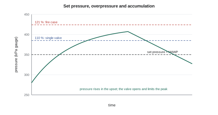
Several pressure terms appear in relief design. The set pressure is the pressure at which the device begins to open; for a single device it is normally no higher than the MAWP. Overpressure is the pressure increase above the set pressure while the device relieves its rated flow. Accumulation is the pressure increase above the MAWP during relief. The code allows the pressure to rise above the MAWP during relief by a limited amount: in general 10 % for a single device, 16 % when multiple devices are used, and 21 % for fire cases. For V-410 with an MAWP of 350 kPa gauge, the maximum relieving pressure is therefore 385 kPa gauge for the non-fire cases with one valve and 424 kPa gauge for the fire case. The sizing in lesson 9 uses those relieving pressures. Blowdown is the difference between the set pressure and the pressure at which the valve closes again, typically a few percent.
Relief devices
Spring-operated relief valves are the most common devices. A spring holds a disc against a nozzle; when the force of the pressure under the disc exceeds the spring force, the valve lifts. Conventional valves are affected by back pressure in the discharge system, which adds to the spring force. Balanced bellows valves use a bellows to cancel the effect of back pressure and are used when back pressure is variable or high. Pilot-operated valves use a small pilot to control a main valve; they open fully at set pressure, hold tightly closed close to the set point and tolerate back pressure, but they are less suitable for dirty or polymerizing services.
Rupture discs are thin membranes designed to burst at a set pressure. They open fully and quickly, have no moving parts and do not leak before bursting, which makes them suitable for runaway reactions, corrosive services and very fast pressure rises. They do not reclose, so the vessel loses its contents until it is isolated. A rupture disc is often placed upstream of a relief valve to protect the valve from corrosion or to prevent leakage of toxic material; the space between them needs a pressure gauge or alarm to detect a leaking disc, because pressure trapped there would raise the disc's burst pressure. Atmospheric tanks use pressure-vacuum vents and emergency vents with large hinged covers that lift in a fire.
| Device | Strengths | Limitations |
|---|---|---|
| Conventional spring valve | Simple, recloses, widely available | Capacity and set pressure affected by back pressure |
| Balanced bellows valve | Tolerates variable back pressure | Bellows can fail; must be vented |
| Pilot-operated valve | Tight shutoff close to set, full lift | Not for dirty or polymerizing fluids |
| Rupture disc | Fast, full opening, leak-tight | Does not reclose; replace after bursting |
| Tank emergency vent | Large area for fire relief of tanks | Low pressure only |
Disposal systems
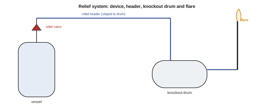
Relief devices must discharge to a safe place. Clean air or steam may go to the atmosphere through a vent stack, but flammable or toxic vapours generally go through a closed header to a knockout drum, which removes liquid, and then to a flare, where they are burned, or to a scrubber. The Texas City disaster involved a blowdown drum that vented hydrocarbons directly to the atmosphere through a stack; when liquid overflowed it, the cloud found an ignition source. Since then, many companies have replaced atmospheric blowdown drums with closed systems and flares. API 521 provides methods for sizing headers, knockout drums and flares, including the radiation from the flare to people and equipment nearby.
The inlet and outlet piping of a relief valve must be designed with care. A rule widely used in practice, from API 520, limits the inlet pressure loss to 3 % of the set pressure, because higher losses make spring valves open and close rapidly, a behaviour called chatter that damages the valve and reduces its capacity. Outlet piping must handle the reaction force of the discharge and must not create so much back pressure that it reduces the valve's capacity. Block valves under relief valves, used to allow maintenance, must be locked open and controlled by procedure; a closed block valve under a relief valve removes the protection completely.
Some vessels cannot use relief devices effectively, for example when the release would be too toxic to discharge or when a reaction is so fast that no practical vent could relieve it. In those cases designers turn to other strategies: designing the vessel to contain the maximum pressure, using a safety instrumented system to stop the reaction or the heat input early, or choosing a different process. Relying on instrumented systems instead of relief requires a high safety integrity level and a careful analysis, and many codes allow it only in specific circumstances.
Keeping relief systems valid
A relief study is a living document. At Kingfisher Bioenergy each relief device has a data sheet showing its scenarios, governing case, required and installed areas, set pressure and inspection interval. When a process change raises throughput, adds a heat source, changes the composition or replaces a pump with a larger one, management of change requires the relief study to be checked. Relief valves are removed and bench tested at intervals set by their service and history, typically every few years, and the results feed the mechanical integrity program. Theo finds that the relief data sheet for V-410 was copied from an older drum of similar size and never updated for the larger reboiler; the next lesson shows what that meant.
Common mistakes
MistakeSizing the relief device for the scenario with the largest mass rate.
InsteadSize for the scenario that needs the largest orifice area.
MistakeAssuming the operator will stop the upset before relief is needed.
InsteadRelief sizing normally gives no credit to operator response.
MistakeLeaving a block valve under a relief valve closed after maintenance.
InsteadLock it open and control it by procedure.
MistakeTreating relief studies as permanent once done.
InsteadRevisit them with every change in process or equipment.
Summary and key terms
- Relief design runs from scenarios to rates, governing case, device, piping and disposal.
- Pressure vessels follow CSA B51 and the TSSA pressure equipment rules, which adopt the ASME Boiler and Pressure Vessel Code; sizing and scenarios follow API 520 and 521; tanks follow API 2000.
- Allowed accumulation is 10 % for a single valve, 16 % for multiple valves and 21 % for fire.
- For V-410 (MAWP 350 kPa gauge) the relieving pressures are 385 and 424 kPa gauge.
- Flammable discharges go through knockout drums to flares; atmospheric blowdown drums were a factor at Texas City.
- MAWP
- The maximum allowable working pressure of a vessel.
- Set pressure
- The pressure at which a relief device begins to open.
- Accumulation
- The pressure rise above the MAWP during relief.
- Governing scenario
- The relief case requiring the largest relief device.
- Rupture disc
- A non-reclosing membrane that bursts at a set pressure.
- Chatter
- Rapid opening and closing of a relief valve, often caused by high inlet loss.
Practice problems
Work each problem on paper first, then reveal the answer to check.
A vessel has MAWP 1,000 kPa gauge. What is the maximum relieving pressure for a fire case?
Show answer
1,210 kPa gauge.
Name four common overpressure causes.
Show answer
Blocked outlet, utility failure, control valve failure, external fire, tube rupture or reaction.
Why are bellows valves used with variable back pressure?
Show answer
The bellows cancels the effect of back pressure on the disc.
What is the inlet loss rule of thumb for relief valves?
Show answer
No more than 3 % of the set pressure.
Why is a pressure gauge placed between a rupture disc and a relief valve?
Show answer
To detect pressure from a leaking disc, which would raise its burst pressure.
What is the role of a knockout drum?
Show answer
To separate liquid from the relief stream before the flare.
Lesson quiz · 5 questions
Score 60% or more to complete this lesson.
Create a free account to save your progress, take quizzes and earn a certificate.