
BLR-330 · Lesson 6 of 12 · 20 min
Heat exchanger maintenance: bundles, bolting and testing
E-2201A is a floating-head shell-and-tube exchanger that heats C-410's feed with the column bottoms. Its bundle is fouled, and the unit has been losing heat for a year: the duty is down by about 30 %, and the furnace has been burning more fuel to make up for it. Desmond Pryce, Ironbridge's exchanger lead, has pulled and retubed more bundles than anybody on site, and he comes over from the shop for the day the bundle comes out. "Pulling a bundle is easy," he says. "Getting it back in, with the right gaskets, the right torque and a test that holds, is the job." This lesson covers turnaround maintenance on shell-and-tube exchangers: taking them apart, pulling and cleaning bundles, inspecting and repairing them, putting them back together with properly made bolted joints, and testing them.
Why exchangers need turnaround work
Exchangers are some of the most common turnaround jobs, because they foul. Process fluids leave deposits of coke, polymer, salts, scale and corrosion products on the tubes, and cooling water leaves scale and biological growth. A thin layer of deposit greatly reduces heat transfer, so a fouled exchanger wastes energy and limits the unit. Exchangers also corrode and erode: tubes thin and leak, tube-to-tubesheet joints loosen, baffles wear, shell nozzles corrode and gasket faces are damaged. Most exchangers can only be cleaned and inspected thoroughly with the unit down.
Earlier courses described the types of exchanger and how bundles are retubed in the shop. On a turnaround the common jobs are opening the exchanger, pulling the bundle, cleaning the bundle and shell, inspecting and testing the tubes, plugging leaking tubes or replacing the bundle, and reassembling and testing. Large exchangers can take several days each, and a unit may have dozens of them, so exchanger work is often on or near the critical path.
| Exchanger type | What comes apart | Turnaround notes |
|---|---|---|
| Fixed tubesheet | Channel covers only; bundle cannot be pulled | Tubes cleaned in place; shell side cleaned chemically |
| U-tube | Channel and bundle | Bundle pulled from one end; U-bends hard to clean mechanically |
| Floating head | Channel, shell cover, floating head cover, bundle | Most flexible; most joints to make up |
| Kettle reboiler | Channel and bundle from a large shell | Long, heavy bundles need careful rigging |
Opening and pulling the bundle
Opening a floating-head exchanger follows a set order. With the exchanger isolated and drained, the crew removes the channel cover and the channel, then the shell cover, which exposes the floating head cover. The floating head cover is unbolted from inside the shell end, and its split backing ring is removed. The bundle can then be pulled out of the shell from the channel end. Every part is tagged, every gasket face is protected as soon as it is exposed, and bolts and nuts are bagged by joint unless the package calls for new ones.
Bundles are pulled with a bundle extractor, a hydraulic machine that grips the tubesheet and draws the bundle out on rails, or with cranes and a pulling rig. The extractor is lifted into place by crane, aligned with the shell and anchored. The bundle is pulled slowly, watching for binding on the baffles and seal strips, and is lifted clear with the extractor or a spreader beam so that it does not bend. A heavy bundle that is lifted from two points without support can sag and damage tubes or baffles.
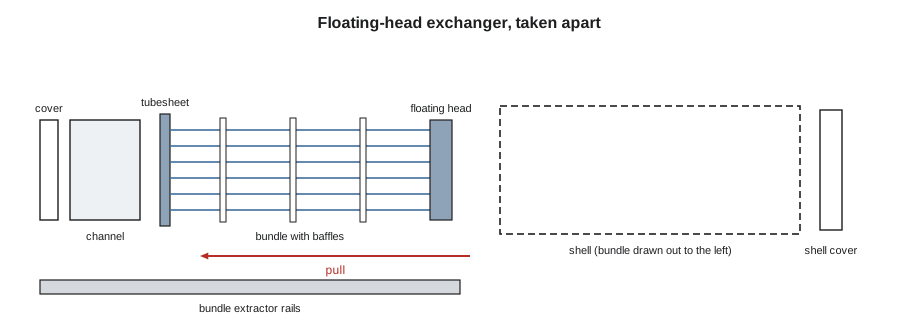
At E-2201A, the March walkdown pays off. The extractor sits on a short platform of crane mats in the gap between the exchanger and the pipe rack, as the updated package shows, and the bundle comes out in under two hours. Its tubes are coated with a hard black layer of coke and asphaltene, and the outer tubes in the bottom rows are almost blocked.
Cleaning and inspecting the bundle
Bundles are usually cleaned by high-pressure water jetting at a cleaning pad, inside the tubes with lances and outside with jets aimed between the tube rows. Heavily fouled bundles may be soaked in chemicals first. The work is done by specialist cleaning contractors, behind barricades, and nobody else may enter the area while jetting is under way. Shell interiors are cleaned at the same time.
Once the bundle is clean, the inspector examines it. Tubes are checked for thinning, pitting and cracks, usually with eddy current testing for non-magnetic tubes or remote field or internal rotary inspection for carbon steel. The tube-to-tubesheet joints are checked for leaks and erosion, the baffles for wear and the gasket faces for damage. Shell nozzles and the shell inside are inspected while the bundle is out. The results decide what happens next: the bundle may be returned to service as it is, have a few tubes plugged, be retubed or be replaced with a spare.
| Finding | Typical decision |
|---|---|
| Light fouling removed, tubes sound | Return to service |
| A few tubes leaking or thin | Plug those tubes at both ends, within the plugging limit |
| Many tubes thin, or plugging limit reached | Retube in the shop or install a spare bundle |
| Damaged gasket face | Machine the face, or repair by weld and machine |
| Shell nozzle corroded | Weld repair or replacement under the repair code |
Tube plugging is a quick fix with limits. Each plugged tube removes heat transfer area and raises the flow through the remaining tubes. Owners set a plugging limit, often around 10 % of the tubes, beyond which the bundle must be retubed or replaced. Plugs must be of a compatible material and installed at both ends, and every plugged tube is recorded on the tubesheet map so that the next inspection knows where they are.
For E-2201A, the eddy current results show that seven tubes have wall loss beyond the owner's limit; they are plugged and mapped. The shell nozzle on the inlet has corroded at its weld, as the inspector expected, and its repair is the critical path of the package. The floating head's gasket face has a radial scratch across the seating surface, which the crew dresses by hand under the inspector's eye rather than risking a leak.
Making up bolted joints
Most exchanger leaks after a turnaround come from joints that were not made up properly. A bolted flange joint seals because the bolts, when tightened, stretch like springs and squeeze the gasket between the flange faces. If the bolts are too loose, the gasket does not seal; if one side is tighter than the other, the flanges tilt and the gasket is crushed on one side and loose on the other; if the gasket face is damaged, no amount of torque will seal it. Making up a joint is therefore a skilled job that follows a procedure.
The industry's guide to assembling bolted joints is ASME PCC-1, whose current edition was published in 2022. It covers cleaning and inspecting the flange faces, checking the gasket, lubricating the bolts and nuts, installing them, tightening them in steps in a set pattern, and recording the work. It also describes how to train and qualify the people who assemble joints. Many owners require joints in critical service to be assembled by qualified bolting technicians, tightened with calibrated tools and recorded on a joint record sheet.
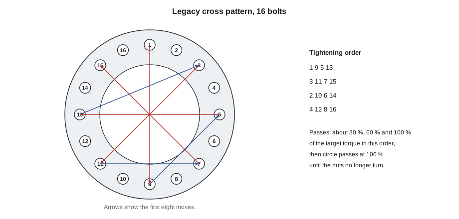
The traditional tightening pattern is the legacy cross pattern, in which bolts are tightened in a star sequence that jumps around the flange, so that each bolt is followed by one roughly opposite it. The torque is raised in steps, typically about 30 %, 60 % and 100 % of the target, and then the bolts are tightened in a circle at the full torque until the nuts no longer turn. PCC-1 also gives alternative patterns that use fewer passes, which save time on large flanges when the owner has shown they work for that joint.
The torque to apply is worked out from the bolt load needed, the bolt size and a nut factor that depends on the lubricant and the thread condition. The simple relation is T = K D F, where T is the torque, K the nut factor, D the nominal bolt diameter and F the bolt load. The nut factor varies widely, so the torques used on site come from the owner's tables for each lubricant, and the scatter in the actual bolt load is large even when the torque is right. That is why the pattern and the passes matter as much as the final torque.
Worked problem
Torque and pattern for the E-2201A channel cover
The channel cover joint has 16 studs of 1 1/4 in nominal size, with a tensile stress area of 645 mm². The target bolt stress is 345 MPa and the nut factor for the lubricant is 0.16. Find the bolt load, the target torque, the torque for each pass and the tightening order, and check the joint record.
Show solution
- Bolt load F is the stress times the stress area.
- Torque T = K D F, converted to the units of the wrench.
- Passes at 30, 60 and 100 percent, then circle passes at 100 percent.
- The cross pattern for 16 bolts follows the bit-reversed numbering.
Answer: The target torque is about 1,130 N·m. The record shows the channel joint complete, the shell cover still waiting for its final check pass, and E-2201B not yet started.
# Bolt load and torque for a channel cover joint, and the tightening order (illustrative values)
N_BOLTS = 16
D = 0.03175                # nominal bolt diameter (m)
STRESS = 345          # target bolt stress (N/mm²)
AREA = 645            # tensile stress area of one bolt (mm²)
K = 0.16               # nut factor for the lubricant used (illustrative)
F = STRESS * AREA      # bolt load
T = K * D * F   # torque
print(f"Load per bolt {F:,.0f} N; target torque {T:,.0f} N·m")
for frac in (0.3, 0.6, 1.0):
    print(f"  pass at {frac:.0%}: {T * frac:,.0f} N·m")

def cross_order(n):
    """Legacy cross pattern for a bolt count that is a power of two (bit-reversed numbering)."""
    bits = n.bit_length() - 1
    assert 1 << bits == n
    return [int(format(i, f"0{bits}b")[::-1], 2) + 1 for i in range(n)]
print("Cross pattern order:", "-".join(map(str, cross_order(N_BOLTS))))
log = [("E-2201A channel", True, 4, True), ("E-2201A shell cover", True, 3, False), ("E-2201B channel", False, 0, False)]   # (joint, gasket fitted, passes done, final check pass)
for j, gasket, passes, check in log:
    status = "complete" if gasket and passes >= 3 and check else "open"
print(f"{j:20} gasket {'yes' if gasket else 'no '} passes {passes} check pass {'yes' if check else 'no '} {status}")Load per bolt 222,525 N; target torque 1,130 N·m pass at 30%: 339 N·m pass at 60%: 678 N·m pass at 100%: 1,130 N·m Cross pattern order: 1-9-5-13-3-11-7-15-2-10-6-14-4-12-8-16 E-2201A channel gasket yes passes 4 check pass yes complete E-2201A shell cover gasket yes passes 3 check pass no open E-2201B channel gasket no passes 0 check pass no open
Testing the exchanger
After reassembly the exchanger is pressure tested. Because it has two sides, the tests are done in a set order. For a floating-head exchanger, the shell side is often tested first with a test ring fitted in place of the shell cover and floating head cover, so that the tube-to-tubesheet joints at the floating end can be seen and checked for leaks. Then the floating head cover and shell cover are fitted, and the tube side and the shell side are tested in turn. The test pressure, medium, temperature and holding time come from the code and the owner's procedure; the inspector witnesses the tests that the inspection plan marks as hold points.
A leak found during the test is not a failure of the test but its purpose. Leaking tube joints are rerolled or plugged, leaking gaskets are replaced, and the test is repeated. When the test passes, the exchanger is drained, the test record is signed and the blinds are ready to come out. Desmond's rule, which he repeats to every new crew, is that no exchanger leaves his hands without a signed test record and a joint record for every flange.
Common mistakes
MistakeLifting a long bundle from two points without support.
InsteadUse the extractor or a spreader beam; an unsupported bundle sags and damages tubes and baffles.
MistakeTightening a flange by going round the circle from the first bolt.
InsteadUse the cross pattern in passes; tightening in a circle from the start tilts the flanges.
MistakeReusing a gasket because it looks fine.
InsteadAlways fit a new gasket of the specified type, size and material.
MistakePlugging tubes without recording them.
InsteadMap every plugged tube so the next inspection and the plugging limit can be tracked.
Summary and key terms
- Exchangers foul, corrode and erode, and are among the most common turnaround jobs.
- Bundles are pulled with extractors or cranes and must be supported to avoid damage.
- Cleaning is usually by high-pressure water jetting by specialist crews; inspection then decides on plugging, retubing or replacement.
- Plugging has a limit, often about 10 % of the tubes, and every plug is mapped.
- Joints are made up to ASME PCC-1: clean faces, new gaskets, lubricated bolts, stepped torque in a cross pattern and circle passes.
- T = K D F links torque to bolt load, but the nut factor varies widely.
- Shell and tube sides are tested in a set order, often with a test ring first.
- Bundle extractor
- A hydraulic machine that draws a tube bundle out of its shell.
- Plugging limit
- The share of tubes that may be plugged before a bundle must be retubed or replaced.
- ASME PCC-1
- The guidelines for assembling pressure boundary bolted flange joints.
- Cross pattern
- A tightening sequence that moves across the flange from bolt to bolt.
- Nut factor
- An empirical factor linking torque to bolt load, which depends on lubrication and threads.
- Test ring
- A fixture that seals the shell so the floating-end tube joints can be seen during a shell-side test.
Practice problems
Work each problem on paper first, then reveal the answer to check.
Why is the shell side of a floating-head exchanger often tested first with a test ring?
Show answer
So that the tube-to-tubesheet joints at the floating end can be seen and checked for leaks.
A bundle of 400 tubes has 36 plugged tubes and 8 more need plugging. What do you report?
Show answer
That would be 44 tubes, 11 % of the bundle, above a 10 % limit; the bundle needs retubing or replacement.
What is the second bolt in the cross pattern for a 16-bolt flange?
Show answer
Bolt 9, directly across the flange from bolt 1.
Why are circle passes done at full torque after the pattern passes?
Show answer
Tightening each bolt relaxes its neighbours a little; circle passes bring them all to the target until the nuts stop turning.
Lesson quiz · 5 questions
Score 60% or more to complete this lesson.
Create a free account to save your progress, take quizzes and earn a certificate.