
BLR-230 · Lesson 8 of 12 · 19 min
Stacks, breeching and ductwork
In July, Kiera leaves Tank 15 for two weeks and goes back to Riverbend, where Dale Whitford is running the Unit 2 stack job. Unit 2's old stack is a brick-lined steel shell that has stood for forty-five years. Its liner is failing, and rather than reline it the plant has bought a new steel stack, 60 m (200 ft) tall and 3.0 m (10 ft) in diameter, to be set on a new foundation beside the old one during the July outage. New breeching will carry the flue gas from the air heater outlet to the new stack, and the old stack will be demolished after the unit is back in service. "A stack is a tank turned on its end and filled with hot gas instead of oil," Dale says. "Except the wind is the load that matters, and it never stops."
What a stack does and how it is built
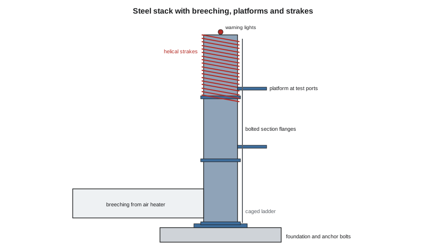
A stack carries flue gas high enough that the plume rises and disperses before it reaches the ground. Its height is set by the plant's environmental approval and dispersion modelling, not by the boilermakers, but almost everything else about how it stands up is boilermaker work. A steel stack is a cylindrical shell of welded plate, thicker at the base where the wind bending is greatest and thinner toward the top. It stands on a base plate bolted to a concrete foundation by a ring of anchor bolts. Inside, it is protected from the hot, often acidic gas by a liner: refractory concrete, a stainless or alloy steel inner flue, or a coating. Outside, it carries ladders and platforms for access, test ports for gas sampling, aircraft warning lights where the height requires them, and lightning protection.
Steel stacks are designed to ASME STS-1 or a similar standard, which covers the shell design, the wind and earthquake loads, the openings, the liners and the dynamic behaviour. Riverbend's stack arrives in three sections, each about 20 m (67 ft) long, with flanged joints. The bottom section has the breeching opening, the base plate and the anchor bolt chairs; the top section has the helical strakes described below.
Wind loads and vortex shedding
Wind pushes on a stack in two ways. The first is drag: the wind pressure on the side of the stack, which bends it like a cantilever and puts the greatest moment at the base, where the anchor bolts and the foundation must resist it. The second is more dangerous to a light steel stack. When wind blows past a cylinder, it sheds vortices alternately from each side, and each vortex pushes the stack sideways, first one way, then the other. The frequency of the vortex shedding rises with the wind speed. If it matches the stack's own natural frequency of vibration, the stack begins to swing across the wind, and the swinging locks the vortices into step with it. A stack can vibrate violently in a steady, moderate wind, and the repeated bending can crack its welds and its anchor bolts in fatigue.
The speed at which this happens is the critical wind speed. It depends on the natural frequency and the diameter, and for a light steel stack it is often a quite ordinary wind. The code below makes a rough estimate for Riverbend's stack, treating it as a uniform steel tube fixed at the base, with a mass allowance for the lining and attachments, and then estimates the drag force at a design gust speed. A stack designer uses far more detailed methods; this is the kind of check a boilermaker can do to understand why the stack has the features it has.
# Riverbend stack: wind on the stack and the vortex shedding check (metric, illustrative)
import math

h = 60.0                  # stack height, m
d = 3.0                  # outside diameter, m
t = 10                  # average shell thickness, mm
E = 200e9                  # steel modulus, Pa
rho = 7850              # steel density, kg/m3
lining = 0.3           # lining and attachments as a fraction of the steel mass

# natural frequency of a uniform cantilever tube
r = d / 2
I = math.pi * r ** 3 * (t / 1000)                 # second moment of area of a thin tube
m = 2 * math.pi * r * (t / 1000) * rho * (1 + lining)  # mass per unit length
fn = (1.875 ** 2 / (2 * math.pi)) * math.sqrt(E * I / (m * h ** 4))
print(f"Natural frequency (first mode): {fn:.2f} Hz")

St = 0.2                 # Strouhal number for a circular cylinder
vcrit = fn * d / St
print(f"Critical wind speed for vortex shedding: {vcrit:.1f} m/s = {vcrit * 3.6:.0f} km/h")

# wind force on the stack at a design gust speed (simple drag estimate)
v = 40.0                  # m/s
air = 1.2
cd = 0.7
q = 0.5 * air * v ** 2
F = q * cd * d * h
print(f"Wind pressure {q:.0f} Pa; drag force {F / 1000:,.0f} kN; base moment {F * h / 2 / 1000:,.0f} kN·m")Natural frequency (first mode): 0.73 Hz Critical wind speed for vortex shedding: 10.9 m/s = 39 km/h Wind pressure 960 Pa; drag force 121 kN; base moment 3,629 kN·m
A natural frequency of about 0.73 Hz gives a critical wind speed of about 39 km/h, a breeze that blows at Riverbend for hundreds of hours every year. Left alone, the stack would vibrate across the wind regularly. The drag force at a design gust is much larger but steady; the vortex load is smaller but repeats millions of times. That is why the stack's top third carries helical strakes: three spiral fins wound around the stack that break up the vortices so that they no longer shed in step along the height. Some stacks use tuned mass dampers instead, heavy weights on springs near the top that absorb the motion.
For the erection crew, the strakes and the dynamic behaviour have two practical consequences. First, the strakes must be complete before the top section is left standing overnight, and a partly erected stack without its top section has a different natural frequency, sometimes in a worse range; Dale's plan sets a wind limit for the stage when only two sections are up. Second, the anchor bolts must be pretensioned to the design value, because loose anchor bolts under a vibrating stack fail in fatigue.
Setting the stack
The foundation, with its anchor bolts cast in, is built by the civil contractor before the outage. Dale's crew checks the bolt circle diameter, the bolt projections and threads, and the elevation of the grout pad, and compares the bolt pattern with the base plate holes on the bottom section, which was checked with a template at the shop. A stack set on a mismatched bolt pattern cannot be fixed by reaming a few holes.
The three sections are lifted by a large crawler crane. The bottom section is set over the anchor bolts on leveling nuts or shims, plumbed in two directions with a theodolite, and the anchor nuts are snugged. The middle section is set on the bottom section's flange, aligned with drift pins, and the flange bolts are installed and tightened in a pattern; then the top section follows. Once the stack is plumb, the base is grouted with non-shrink grout under the base plate. When the grout has cured, the anchor bolts are pretensioned to the designer's value, usually with a hydraulic tensioner, and the flange bolts are brought to their final tension, as lessons 9 and 10 describe.
| Stage | Hold point |
|---|---|
| Foundation handover | Anchor bolt circle, projection, threads and elevation checked |
| Bottom section set | Plumb in two directions; leveling nuts set; area under base clear for grout |
| Each flange joint | Faces clean and aligned; bolts installed and tightened in pattern; gap checked |
| Top section set | Strakes complete; temporary wind limit lifted |
| Grouting | Grout placed and cured to the manufacturer's time |
| Anchor bolt tensioning | Tension to the design value; nuts locked; record signed |
Breeching and ductwork
Breeching is the duct that carries flue gas from the boiler or air heater to the stack. It is usually rectangular, made of plate about 6 mm (1/4 in) thick, stiffened on the outside by a grid of angles or channels so that the flat sides do not bulge or pant under the gas pressure and the vibration from the fans. Riverbend's new breeching is 3.0 m by 3.6 m (10 ft by 12 ft) in section and about 28 m (90 ft) long, built from shop-fabricated sections with flanged ends that are lifted into place and either bolted with gaskets or seal-welded in the field.
Hot gas makes ducts grow. A steel duct carrying gas at 150 to 200 °C (300 to 400 °F) grows by tens of millimetres over its length, and the boiler, the air heater and the stack all move differently as they heat up. Expansion joints absorb this movement. A fabric expansion joint is a belt of high-temperature fabric clamped between two duct flanges; a metal expansion joint is a corrugated steel bellows. Expansion joints arrive with shipping bars that hold them at their installed length. The bars must be left on until the joint is fully welded or bolted in, and then removed before the unit starts, every one of them, because a joint left locked by its shipping bars will push the ducts or tear itself apart on the first start-up.
Flue gas below its acid dew point condenses sulphuric acid on cold metal, and a breeching that runs cold at its corners or stiffeners corrodes through quickly. The breeching is therefore insulated and clad, and the welds that seal the duct must be continuous, because a pinhole lets cold air in and creates a cold, wet, corroding spot. Ducts also carry dampers, doors for inspection, drains at the low points and test ports. The test ports on the stack or the breeching are located by the sampling standard, a set number of duct diameters downstream and upstream of any bend or obstruction, so that the gas flow at the ports is even. In Canada, these locations come from Environment and Climate Change Canada's reference methods and the provincial approval, and the plant's environmental staff check them before the ports are cut.
Worked problem
Thermal growth of a duct
A breeching run is 28 m (90 ft) long and heats from 15 °C (60 °F) to 175 °C (350 °F). Steel grows about 12 × 10⁻⁶ per °C (6.7 × 10⁻⁶ per °F). How much does it grow?
Show solution
- Temperature rise: 175 − 15 = 160 °C.
- Growth: 28 × 1,000 × 12 × 10⁻⁶ × 160 = 54 mm.
Answer: About 54 mm (2.1 in), which the expansion joint must absorb.
Working on and around a stack
Stack work brings together several of the hazards Kiera met in her safety course. The crane lifts are critical lifts under the plan from Rigging and Lifting for Boilermakers, with the crawler crane working close to its chart at the top section. Work on the stack flanges is done from a man basket or a platform on the stack, with fall protection tied off to the stack's own ladder rails only where they are rated for it. The breeching connection to the air heater outlet is made with Unit 2 shut down and isolated, and the inside of the duct is a confined space with flue gas residue, ash and possibly carbon monoxide from the other unit's leaking dampers, so it is tested and ventilated before entry. Dale's job plan shows each of these with its permit and its controls, and his morning meeting goes through the day's lifts and entries one by one.
Common mistakes
MistakeLeaving a stack's top section off overnight in rising wind without checking the plan.
InsteadA partly erected stack has a different natural frequency; follow the plan's wind limit for each stage.
MistakeGrouting the base after the anchor bolts are fully tensioned.
InsteadPlumb, grout, let the grout cure, then pretension the anchor bolts.
MistakeLeaving shipping bars on an expansion joint.
InsteadRemove every shipping bar after the joint is installed and before start-up.
MistakeTreating breeching seal welds as cosmetic.
InsteadA pinhole lets cold air in and starts acid corrosion; seal welds must be continuous.
Summary and key terms
- A steel stack is a welded shell on a bolted base, lined inside and fitted with ladders, platforms and test ports.
- Wind loads a stack by drag and by vortex shedding; at the critical wind speed it can vibrate across the wind.
- Helical strakes or tuned mass dampers prevent vortex vibration on light steel stacks.
- Stacks are set in sections, plumbed, grouted, and then their anchor bolts are pretensioned.
- Breeching is stiffened rectangular duct; expansion joints absorb thermal growth and their shipping bars must be removed.
- Breeching is sealed and insulated to prevent acid dew point corrosion; test ports go where the sampling standard says.
- Breeching
- The duct carrying flue gas from a boiler or air heater to its stack.
- Vortex shedding
- The alternate release of vortices from each side of a cylinder in wind.
- Critical wind speed
- The wind speed at which vortex shedding matches a structure's natural frequency.
- Helical strake
- A spiral fin wound around a stack to break up vortex shedding.
- Expansion joint
- A flexible duct section that absorbs thermal movement.
- Acid dew point
- The temperature below which acid condenses from flue gas.
Practice problems
Work each problem on paper first, then reveal the answer to check.
Why does a light steel stack need strakes when a heavy concrete chimney may not?
Show answer
The light steel stack has a low natural frequency and little damping, so vortex shedding at ordinary wind speeds can make it vibrate; strakes break up the vortices.
What is the order for the base of a stack: grout, plumb, pretension?
Show answer
Plumb, then grout, then pretension the anchor bolts after the grout has cured.
A stack has a natural frequency of 1.0 Hz and a diameter of 2.0 m (6.5 ft). With a Strouhal number of 0.2, what is its critical wind speed?
Show answer
1.0 × 2.0 ÷ 0.2 = 10 m/s, or 36 km/h.
What must happen to an expansion joint's shipping bars?
Show answer
They stay on until the joint is installed, then all of them are removed before start-up.
Lesson quiz · 5 questions
Score 60% or more to complete this lesson.
Create a free account to save your progress, take quizzes and earn a certificate.