
BLR-230 · Lesson 7 of 12 · 19 min
Nozzles, manways and tank appurtenances
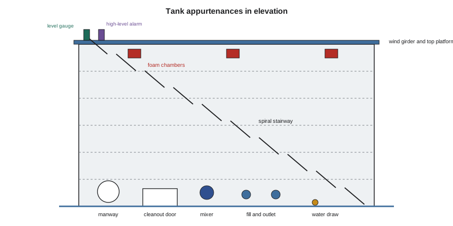
A bare shell is not a tank. Before Tank 15 can store crude, it needs a way for the oil to get in and out, a way for people to get in and out, and a long list of other attachments: stairways and platforms, gauges and alarms, mixers, drains, fire protection, grounding and the fittings for the floating roof. These are called appurtenances. Owen's data sheet for Tank 15 lists forty-three of them, each with a size, an orientation angle and an elevation. In July, while the welding crew finishes the shell, Bernie puts Kiera with the crew that lays out and installs them.
Shell openings and reinforcement
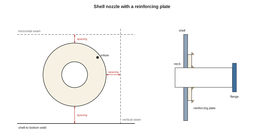
Every hole cut in a shell removes metal that was carrying hoop stress, so every opening above a small size is reinforced. The usual way is a reinforcing plate, often called a pad: a ring of plate the same thickness as the shell, rolled to the shell's curve, fitted around the nozzle neck and welded to the shell around its outer edge and to the neck at the opening. The pad replaces the area of shell removed. Each pad has a small threaded telltale hole. After welding, the space between the pad and the shell is pressurized with air through the telltale at a low pressure, about 100 kPa (15 psi), and the welds are soaped, to prove them tight. The hole is left open in service so that a leak through the shell under the pad shows up instead of corroding unseen.
In thick plate, or for large openings, the reinforcement can be built into an insert plate instead: a thicker section of shell plate with the opening already cut, butt-welded into the course in place of a normal plate. The standard requires some openings in thick lower courses to be stress-relieved as a welded assembly before they are installed, because a large nozzle welded into thick plate leaves high residual stresses. Those assemblies are built in the shop and arrive ready to weld in.
Spacing from other welds
Openings and their reinforcement must be kept away from the shell seams and from each other. Welds close together interact: their heat-affected zones overlap, their residual stresses add, and an inspector cannot examine either one properly. API 650 sets minimum spacings between the welds around an opening and the shell's vertical seams, horizontal seams and shell-to-bottom weld, generally as the larger of a fixed distance and a multiple of the shell thickness, with special rules for low-type nozzles and cleanout fittings that must sit close to the bottom. The spacings are part of the tank's design, but the erector is the one who finds out when a design or a field change breaks them, because only the erector knows exactly where the seams ended up.
Before any opening is cut in Tank 15's bottom course, Kiera checks each one against Bernie's rule for this job, which is the larger of 250 mm (10 in) or eight times the plate thickness. The table in the code gives each opening's centre elevation, the outside radius of its reinforcement and the distance from its centre to the nearest vertical seam as built.
# Tank 15 shell openings: spacing checks before the openings are cut (metric, illustrative rules)
t = 17                         # bottom course thickness, mm
min_edge = max(250, 8 * t)      # weld-to-weld spacing used here: the larger of 250 mm or 8t, mm

# opening: (name, centre elevation, outside reinforcement radius, nearest vertical seam distance), mm
openings = [("Manway A", 1_000, 750, 2_300), ("Mixer M1", 1_100, 750, 1_500), ("Fill N1", 1_700, 520, 3_200), ("Water draw", 500, 250, 1_800)]
course_top = 2_400                # top of the bottom course, mm
for name, elev, rr, seam in openings:
    to_bottom = elev - rr                 # reinforcement edge to the shell-to-bottom weld
    to_horiz = course_top - (elev + rr)   # reinforcement edge to the first horizontal seam
    to_vert = seam - rr                   # reinforcement edge to the nearest vertical seam
    worst = min(to_bottom, to_horiz, to_vert)
    verdict = "clear" if worst >= min_edge else "move the opening or redesign"
    print(f"{name:12} bottom {to_bottom:6.0f}  horiz {to_horiz:6.0f}  vert {to_vert:6.0f}  -> {verdict}")
print(f"Spacing required: {min_edge:.0f} mm")Manway A bottom 250 horiz 650 vert 1550 -> clear Mixer M1 bottom 350 horiz 550 vert 750 -> clear Fill N1 bottom 1180 horiz 180 vert 2680 -> move the opening or redesign Water draw bottom 250 horiz 1650 vert 1550 -> clear Spacing required: 250 mm
The fill nozzle N1 fails: its pad would come within 180 mm (8 in) of the horizontal seam between courses 1 and 2. On the first design drawing it was clear, but that drawing showed a smaller pad; when the fill line was upsized and a larger nozzle and pad were ordered, nobody re-checked the spacing. Kiera brings it to Bernie, Bernie to Owen, and Owen moves N1 down 100 mm (4 in), which clears the seam and keeps the nozzle above the floating roof's legs. The change goes on the drawing before the hole is cut. "That's exactly why we check," Bernie says. "Nobody can fix a hole in the wrong place."
Manways and cleanout doors
Manways let people and equipment into the tank for construction, inspection and cleaning. Shell manways in the bottom course are usually 600 mm (24 in) or 750 mm (30 in) in diameter, with a bolted cover and a davit or hinge to swing it. Roof manways on a fixed roof and pontoon manways on a floating roof are smaller. A flush-type cleanout fitting is a large rectangular opening at the bottom of the shell, flush with the bottom, that lets a cleaning crew push sludge out and bring equipment in. It is a complex, heavily reinforced assembly, usually stress-relieved, with its own reinforced bottom plate.
During construction, a temporary door sheet is often left out of the bottom course, or cut into it, so that the crew can bring equipment and materials in and out. The door sheet is welded back in before the hydrotest, with its seams examined like any other shell seam. Once the door sheet is in and the roof is on, entry is by manway only, under a confined space permit.
The appurtenances list
| Appurtenance | Purpose | What the erector watches |
|---|---|---|
| Fill and outlet nozzles | Product in and out | Orientation, elevation, flange face square and level |
| Water draw-off sump | Removes water that settles from the crude | Sump below the bottom, sealed into the foundation |
| Side-entry mixers | Keep sludge and wax suspended | Pad and nozzle angle to the drawing; clear of roof legs |
| Gauge well and guide pole | Level gauging, sampling and roof guidance | Plumb to 1/200; slotted pole lined up with the roof |
| Level gauge and high-level alarms | Inventory and overfill protection | Independent high-high alarm and its mounting |
| Spiral stairway and platforms | Access to the top of the shell | Supports clear of seams; bolting to the specification |
| Rolling ladder and track | Access to the floating roof | Track level; ladder free over the full roof travel |
| Wind girder | Stiffens the top of an open-top shell | Welded to the shell as designed; often also a walkway |
| Foam chambers and rim seal detection | Fire protection | Location to the fire protection drawing |
| Shunts and grounding | Bond the roof to the shell for lightning and static | Installed to the specification; not left off |
Overfill protection deserves special mention. A tank that is overfilled spills product over its top or forces its floating roof up against the top of the shell, and some of the worst tank farm accidents have started that way. Terminals follow API 2350, which sets levels for normal fill, alarms and the automatic overfill prevention system, with an independent high-high alarm that does not rely on the normal gauge. The erector does not set the levels, but installs the gauge and alarm fittings and leaves the gauge well and the alarm mountings exactly as designed.
Wind girders, stairways and attachments
An open-top tank, like an external floating roof tank, has no roof to keep the top of the shell round, so API 650 requires a wind girder: a stiffening ring around the outside of the shell near the top, sized by the designer for the tank's diameter and the site's design wind speed. Tall shells may also need intermediate wind girders lower down. On Tank 15, the top wind girder is wide enough to walk on and carries the handrail; it is welded to the shell with fillet welds, continuous on top so that it does not trap water.
Every attachment welded to a shell is a weld on a pressure boundary, even if the attachment itself carries no pressure. Stair supports, platform brackets, insulation clips and ladder track brackets are welded to the shell with the same qualified procedures as the seams, kept clear of the shell seams, and never added in the field without approval. A clip welded across a vertical seam can start a crack in exactly the weld that carries the hoop load. The stairway itself, its stringers and treads and its platform framing, is bolted, as lesson 9 describes.
Worked problem
Moving an opening to clear a seam
A nozzle's reinforcing pad has an outside radius of 520 mm (20 in) and its centre is 1,700 mm (68 in) above the bottom. The horizontal seam is 2,400 mm (96 in) above the bottom and the required spacing is 250 mm (10 in). How far down must the nozzle move?
Show solution
- Top of the pad: 1,700 + 520 = 2,220 mm.
- Clearance to the seam: 2,400 − 2,220 = 180 mm.
- Shortfall: 250 − 180 = 70 mm.
- Owen chose a round 100 mm (4 in) move, giving 280 mm of clearance.
Answer: At least 70 mm (2 in); Owen moved it 100 mm (4 in).
Installing a nozzle
Kiera installs her first shell nozzle on Tank 15 with Joanne Pellerin, who comes out from the shop for a week to help with the layout. The sequence is the same for every opening. First the centre is laid out from the tank's reference by its orientation angle, measured around the shell as an arc length from the reference mark, and by its elevation above the bottom, measured from the shell-to-bottom weld. Joanne has Kiera check the arc length against a second measurement from the nearest vertical seam, so that a mistake in either measurement shows up. The spacing to the seams is checked again with the real pad in hand. Then the hole is marked and cut with a track-mounted torch, the edge is ground to the bevel the drawing shows, and the nozzle neck is fitted square to the shell and level, with its flange face set to the projection on the drawing. The pad, rolled to the shell radius, is fitted over the neck, tacked, and welded around its outer edge and to the neck, in a sequence that keeps the heat balanced.
Before the pad is tested through its telltale, the neck-to-shell weld inside the tank is examined, because once the pad is on, the outside of that weld is hidden. Then the telltale is connected to a regulated air supply, the space behind the pad is brought to the test pressure, and every weld is soaped. Joanne's last check is the flange: its bolt holes must straddle the vertical and horizontal centrelines, as the drawing shows, so that the piping that will connect to it lines up.
Openings added after a tank is in service are a different matter. A new nozzle in an existing tank is an alteration under API 653, with its own rules for the plate's condition, the spacing from existing welds, examination and testing, and often a requirement for a hydrotest or an engineering evaluation in place of one. Kiera will meet those rules when Ironbridge comes back to the terminal for repair work in later years.
Common mistakes
MistakeCutting an opening from the design drawing without checking the as-built seams.
InsteadMeasure the seams where they are and check every opening's spacing before cutting.
MistakePlugging the telltale hole after the pad test.
InsteadLeave it open so that a leak under the pad shows itself.
MistakeWelding a clip or bracket to the shell without approval.
InsteadEvery shell attachment needs a qualified procedure, clearance from the seams and approval.
MistakeLeaving out the roof-to-shell shunts because the roof is grounded through the ladder.
InsteadInstall all the bonding the specification calls for; lightning and static need low-resistance paths.
Summary and key terms
- Openings are reinforced with pads or insert plates; pads are tested through a telltale hole that stays open.
- Openings must be kept a set distance from shell seams, the bottom weld and each other.
- The erector checks spacing against the as-built seams and raises any conflict before cutting.
- Manways, cleanout doors and the temporary door sheet give access; the door sheet goes back in before the test.
- Appurtenances include nozzles, sumps, mixers, gauges and alarms, stairways, wind girders, fire protection and bonding.
- Every attachment welded to the shell follows qualified procedures and stays clear of the seams.
- Appurtenance
- Any fitting or attachment on a tank: nozzles, manways, stairways, gauges and so on.
- Reinforcing plate
- A plate welded around a shell opening to replace the shell area removed.
- Telltale hole
- A small hole in a reinforcing plate used to test its welds and to show leaks in service.
- Insert plate
- A thicker shell plate with an opening, butt-welded into a course in place of a pad.
- Flush-type cleanout
- A large reinforced opening at the bottom of the shell, flush with the bottom.
- Wind girder
- A stiffening ring near the top of an open-top tank shell.
Practice problems
Work each problem on paper first, then reveal the answer to check.
Why is a telltale hole left open in service?
Show answer
So that a leak through the shell under the pad drains and shows instead of corroding unseen.
What is the spacing rule on this job for 12 mm (1/2 in) plate?
Show answer
The larger of 250 mm or 8t; 8 × 12 = 96 mm, so 250 mm.
Why is a temporary door sheet used during construction?
Show answer
To let equipment and materials in and out of the tank; it is welded in and examined before the hydrotest.
What standard sets overfill protection levels for terminal tanks?
Show answer
API 2350.
Lesson quiz · 5 questions
Score 60% or more to complete this lesson.
Create a free account to save your progress, take quizzes and earn a certificate.