
BAS-220 · Lesson 6 of 12 · 25 min
PID blocks and loop configuration
▶ Video coming soon A video version of this lesson is on the way.
On Thursday, October 1, Callie spent the afternoon at Quillon's office with Sophie, configuring the PID blocks in the new RTU-1 program and reviewing the loops in Tilden Hall's AHU-1 program. BAS-130 had taught Callie what proportional, integral and derivative action do and how to tune a loop. This session was about the block itself: the dozen or so settings that sit around the gains and decide whether a well-tuned loop behaves well in a real building. "Tuning gets the attention," Sophie said. "Configuration decides what happens at start-up, at shutdown, when someone takes the loop into manual, and when the valve hits its end stop. That's where the trouble is."
Anatomy of a PID block
A PID block in a building automation tool has a recognizable set of pins and parameters, though the names vary between products. The process variable and setpoint come in on the left; the output leaves on the right. Inside are the tuning parameters from BAS-130, and around them are the settings for direction, limits, enabling, tracking and timing.
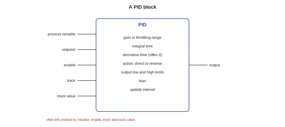
| Setting | What it does | Typical choice in HVAC |
|---|---|---|
| Gain or throttling range | How strongly the output responds to error (BAS-130) | From tuning |
| Integral time | How fast the output keeps moving while error persists | From tuning |
| Derivative time | Response to the rate of change of error | Usually zero in HVAC |
| Action | Direct: output rises as PV rises above SP. Reverse: output rises as PV falls below SP | Cooling direct, heating reverse |
| Output limits | Low and high limits on the output | 0 and 100, or tighter where the device must stay open or closed |
| Bias | Output when error is zero in P-only control | 0 or 50, depending on the product |
| Enable | Turns the calculation on or off | Tied to fan proof or mode |
| Track and track value | Forces the output to a given value while tracking | Used for start-up and shutdown positions |
| Update interval | How often the loop recalculates | Usually the scan, or a few seconds for slow loops |
Direct and reverse action
Every loop has a direction. A cooling valve should open more as the air gets warmer than setpoint: the output rises as the process variable rises, which most tools call direct action. A heating valve should open more as the air gets colder: the output rises as the process variable falls, called reverse action. Some products define the words the other way round, or describe the direction in terms of the error, so the safest check is not the word but the behaviour: raise the process variable above setpoint in simulation and see which way the output moves.
A loop set the wrong way is easy to spot once it is running, because it drives its output to one end and stays there. A heating loop set to direct action closes the valve as the room gets colder, which makes the room colder still, until the valve is fully closed and the room is freezing. The fault is less obvious on the bench, where nothing physical responds, which is why Sophie checks the direction of every loop in simulation, as lesson 11 describes, before the controller goes to site.
What the output does: proportional and integral in numbers
BAS-130 described the proportional term as gain times error and the integral term as a contribution that grows while the error lasts. Seeing the numbers helps to read a block's behaviour from a trend. In the common form used in HVAC tools, the proportional contribution is the gain times the error, and the integral contribution grows each second by the proportional contribution divided by the integral time.
Worked problem
Reading P and I contributions
RTU-1's economizer loop on discharge air temperature has a gain of 4 per kelvin and an integral time of 120 seconds, with direct action. The discharge air is 1.5 K above setpoint. What is the proportional contribution? If the error were held at 1.0 K for 60 seconds, how much would the integral term add?
Show solution
- P term: 4 × 1.5 = 6.0, so the output is 6.0 above its bias.
- I term growth: 4 × 1.0 ÷ 120 = 0.0333 per second.
- Over 60 s: 0.0333 × 60 = 2.0.
Answer: A proportional contribution of 6.0 and an integral addition of 2.0 over the minute. On a trend, the output steps by the P term when the error appears and then ramps steadily while the error persists; that ramp is the integral working.
Gains are expressed in different ways in different products. A gain of 4 per kelvin is the same as a throttling range of 25 K, because 100 ÷ 4 = 25: the output would travel its full 100 over 25 K of error with proportional action alone. Some tools express gain as output units per degree, some use throttling range, some use a dimensionless gain on scaled values. When copying tuning from one product to another, convert carefully, as BAS-130 warned.
Output limits and anti-windup
Output limits stop the loop asking for more than the device can give or more than the sequence allows. Usually they are 0 and 100. Sometimes the low limit is above 0, for example to keep a minimum flow through a coil in freezing weather, and sometimes the high limit is below 100, for example when another loop has a share of the same device. Limits on the output are not the same as a clamp after the block. A clamp after the block limits what the device sees but leaves the loop's internal integral free to keep growing. Limits inside the block tell the loop where the end stops are.
Integral windup, which BAS-130 described at AHU-1 on October 9, happens when the integral term keeps accumulating while the output is already at a limit or the process cannot respond. When the process finally responds, the loop overshoots badly while the integral unwinds. Good PID blocks have anti-windup built in: when the output reaches a limit, the integral stops growing in that direction. The block can only do this if it knows the limits, which is one reason to set them inside the block. The other cause of windup, a loop running while its equipment is off, is solved by enabling and tracking.
Enable, track and bumpless transfer
A loop should only calculate when its equipment is running and able to respond. The enable input turns the calculation on and off. When a loop is disabled, its output must go somewhere sensible, and that is the job of tracking. While the track input is true, the output follows the track value, and the integral term is set so that the output stays there without a jump when tracking ends. Lesson 1's restart logic and BAS-130's start-up fix used exactly this.
(* AHU-1 heating loop enable : added after the October 9 windup *)
HeatLoop.Enable := FanProven AND ProofTimer.Q;     (* 30 s after proof *)
IF NOT HeatLoop.Enable THEN
    HeatLoop.Track := TRUE;      (* output follows TrackValue *)
    HeatLoop.TrackValue := 0.0;  (* valve closed when the fan is off *)
ELSE
    HeatLoop.Track := FALSE;
END_IF;
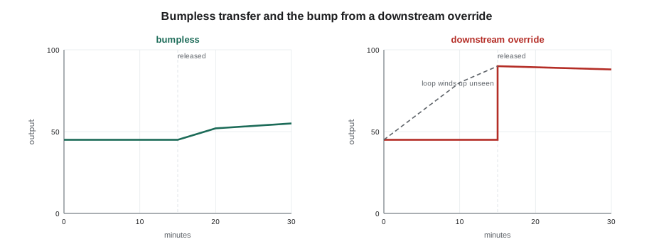
Bumpless transfer means that when a loop changes state, from tracking to automatic, from manual to automatic, or from one setpoint to another, its output continues smoothly from where it was instead of jumping. A loop that has been in manual at 45 and is returned to automatic should start from 45 and move gradually, not leap to whatever its stored integral last said. Most PID blocks do this when tracking is used correctly. Problems arise when someone overrides the output point downstream of the block instead of using the block's own manual or track inputs: the block keeps calculating, unaware that its output is being ignored, and when the override is released the device jumps to the block's wound-up value.
Worked problem
The cost of an override downstream of the loop
Suppose that during a filter change on AHU-1, an operator overrides the heating valve output point at 45 for 40 minutes. The heating loop, still enabled, sees the discharge air 2 K below setpoint the whole time. With a gain of 4 per kelvin and an integral time of 120 seconds, roughly how much does the integral term try to add? What happens when the override is released?
Show solution
- Integral growth: 4 × 2 ÷ 120 = 0.0667 per second.
- Over 40 minutes, 2,400 s: 0.0667 × 2,400 = 160, far beyond the 100 limit.
- With anti-windup, the integral stops when the output reaches 100.
Answer: The loop's output has risen to its 100 limit while the device sat at 45. When the override is released, the valve jumps from 45 to 100, and the discharge air overshoots. Overriding the loop's own manual input, or tracking, avoids the bump.
Update interval and filtering
Many PID blocks let the programmer set how often the loop recalculates. Recalculating every scan suits fast loops; slow loops such as a space temperature loop can recalculate every few seconds or even every minute without harm, and doing so reduces actuator wear from tiny corrections. The process variable can also be filtered, either at the input point, as BAS-210 described, or inside the block. A little filtering removes noise; too much adds lag, which BAS-130's Ninefield pump loop showed with its 15 second filter. The filter time should be small compared with the process's own response.
Common configuration faults
By the end of the afternoon, Sophie and Callie had checked eleven loops across the two programs. Three needed changes: a cooling valve loop at Tilden with its output limits set outside the block as a clamp, a fan coil heating loop in the Morrow House program with no enable, and one RTU-1 loop copied from another product whose gain had not been converted. AHU-1's own heating loop had an enable, but it was tied to the fan command rather than the fan proof, and that weakness only showed itself a week later, in the October 9 windup that BAS-130 described; the listing above is the fix made that day. Sophie kept a checklist she ran on every new loop, and Callie copied it into her notebook.
| Check | What to look for |
|---|---|
| Direction | In simulation, PV above SP moves the output the right way |
| Units of gain | Converted correctly from the source of the tuning |
| Limits inside the block | Output limits set in the block so anti-windup works |
| Enable | Tied to equipment proof or mode, with a short delay after proof |
| Track value | A safe position when disabled: closed, minimum or failsafe |
| Manual handling | Operators use the loop's own manual or track, not downstream overrides |
| Update interval and filter | Suited to the speed of the process |
| Trend | PV, SP and output trended together for tuning and later checks |
Sequencing one loop across two devices
Some loops drive more than one device in sequence. A single discharge air loop on an air handler with an economizer and a cooling coil might use the first part of its output to open the outdoor air dampers and the second part to open the cooling valve, so that free cooling is used before mechanical cooling. The PID block produces one output from 0 to 100, and scaling blocks from lesson 5 split it: 0 to 50 becomes damper 0 to 100, and 50 to 100 becomes valve 0 to 100. The split must be clamped at each end, and the order must match the sequence. A split set the wrong way round opens the cooling valve before the free outdoor air, which works but wastes energy every day it runs.
Worked problem
Splitting one loop output
A loop output of 0 to 50 drives the economizer dampers from their minimum to fully open, and 50 to 100 drives the cooling valve from 0 to 100. What do the damper and valve receive at a loop output of 30, and at 70?
Show solution
- At 30: damper share = 30 ÷ 50 = 0.6 of its range; valve = 0, because the output is below 50.
- At 70: damper fully open; valve = (70 − 50) ÷ 50 × 100 = 40.
Answer: At 30, the dampers are 60 in 100 of the way from minimum to fully open and the valve is shut. At 70, the dampers are fully open and the valve is at 40.
Common mistakes
MistakeTrusting the words direct and reverse without testing.
InsteadRaise the process variable above setpoint in simulation and confirm the output moves the right way.
MistakeClamping the output after the block instead of setting limits in it.
InsteadSet output limits inside the block so its anti-windup knows the end stops.
MistakeLeaving a loop running while its equipment is off.
InsteadEnable the loop from equipment proof and track a safe value while disabled.
MistakeOverriding the output point downstream of the loop.
InsteadUse the loop's own manual or track inputs so it does not wind up while ignored.
MistakeCopying gains between products without converting units.
InsteadConvert gain, throttling range and integral time to the new product's conventions.
Summary and key terms
- A PID block has tuning parameters plus settings for action, limits, bias, enable, tracking and update interval.
- Direct action raises the output as the process variable rises; reverse action raises it as the process variable falls.
- The P term is gain times error; the integral grows each second by the P term divided by the integral time.
- A gain per degree and a throttling range are two views of the same setting: throttling range = 100 ÷ gain.
- Limits inside the block let anti-windup stop the integral at the end stops.
- Enable and tracking keep loops quiet when equipment is off and give bumpless starts.
- Downstream overrides leave the loop calculating unseen and cause a bump on release.
- Direct action
- Loop action in which the output rises as the process variable rises above setpoint.
- Reverse action
- Loop action in which the output rises as the process variable falls below setpoint.
- Output limits
- Low and high limits on a loop's output, set inside the block.
- Anti-windup
- A feature that stops the integral term growing when the output is at a limit.
- Tracking
- Forcing a loop's output to follow a given value while setting its integral to match.
- Bumpless transfer
- A change of loop state without a sudden jump in output.
- Bias
- The output of a proportional-only loop when the error is zero.
- Update interval
- How often a loop recalculates its output.
Practice problems
Work each problem on paper first, then reveal the answer to check.
A heating valve loop. Direct or reverse action?
Show answer
Reverse: the output rises as the temperature falls below setpoint.
A gain of 5 per kelvin. What throttling range is that?
Show answer
100 ÷ 5 = 20 K.
Gain 4 per K, integral time 120 s, error 0.5 K for 120 s. How much does the integral add?
Show answer
4 × 0.5 ÷ 120 × 120 = 2.0.
Why set output limits inside the PID block?
Show answer
So that anti-windup stops the integral at the limits.
What should a heating loop's output do when its fan stops?
Show answer
Track a safe value, normally a closed valve, unless freeze protection requires otherwise.
Lesson quiz · 5 questions
Score 60% or more to complete this lesson.
Create a free account to save your progress, take quizzes and earn a certificate.