
BAS-220 · Lesson 12 of 12 · 25 min
Programming a variable air volume box
▶ Video coming soon A video version of this lesson is on the way.
On Thursday, November 12, room 108 in Tilden Hall was too hot. BAS-110 told how Callie and Prakash walked the building from the plant to the zone and found the cause: the actuator on VAV-1-08's hot water reheat valve had slipped on its valve stem, so the valve was stuck open while the program commanded it closed. They re-clamped and marked it the next morning. On Saturday, November 14, at the last workshop of the autumn, Sophie brought the trends from room 108 and the findings list Callie had written two weeks earlier, in lesson 10, and set the morning's task: write a new program for VAV-1-08 that would do the job better and say so if it could not. This lesson brings the whole course together in one terminal unit: modes, loops, scaling, limits, timers, alarms, trends and testing.
What the trends showed
The trends of November 12 told the story once Callie knew what to look for. From about 10:00 the room temperature climbed from 23 °C to 26 °C. The cooling loop rose to 100, and the airflow setpoint followed it to the box's maximum, which someone had raised the day before from its design 150 L/s to 200 L/s; the measured airflow matched. The heating loop stayed at 0 and the valve command at 0. Everything the program could see said it was cooling as hard as it could. What it could not see was hot water flowing through a coil whose valve was commanded shut, heating 200 L/s of cool supply air before it reached the room.
Two lessons followed. The first was that the old program had no way to notice that something was wrong: it could only do more of the same. A simple fault rule, watching for a room that stays too warm while the box is at full cooling and the heating is commanded off, would have raised a useful alarm on the first morning instead of waiting for a complaint. The second was the reheat energy wasted while it happened, which an example below estimates.
Worked problem
Estimating the heat wasted by a stuck-open reheat valve
While the valve was stuck open, the box delivered 200 L/s. Suppose the coil warmed the air from the 13 °C supply temperature to about 24 °C, an 11 K rise. Using the common air heat formula q ≈ 1.2 × L/s × ΔT in watts, how much heat did the coil add? Over a 6 hour day?
Show solution
- q ≈ 1.2 × 200 × 11 = 2,640 W, or about 2.6 kW.
- Over 6 hours: 2.64 × 6 = 15.84 kWh, about 15.8 kWh of heat, all of which the central cooling then had to remove.
Answer: About 2.6 kW of unwanted heat, nearly 16 kWh in a day, paid for twice: once in heating and again in cooling. One stuck valve in one room is small; the same fault unnoticed across a building is not.
Single maximum and dual maximum
Lesson 10 found that VAV-1-08's 2009 program used a single-maximum sequence. In cooling, airflow rises from the minimum to the cooling maximum as the cooling loop rises. In heating, airflow stays at the minimum and the reheat valve opens on the heating loop, so all the heating is done with the minimum airflow. That is simple, but it has two weaknesses. To deliver enough heat at a low airflow, the discharge air must be very warm, and very warm air from ceiling diffusers tends to stay near the ceiling instead of mixing into the room. And the minimum airflow is set high enough for heating, so the box moves more air than it needs in the deadband between heating and cooling, which wastes fan energy and, in many buildings, reheat.
A dual-maximum sequence, described in ASHRAE Guideline 36 for VAV boxes with reheat, handles heating in two stages. In the first half of the heating loop, airflow stays at the minimum while the discharge air setpoint rises from the air handler's supply temperature towards a maximum, which is held a limited amount above room temperature so that the warm air still mixes into the room. In the second half, the discharge temperature stays at that maximum and the airflow rises from the minimum to a separate heating maximum. The minimum airflow can then be set for ventilation rather than for heating. Guideline 36, most recently published as Guideline 36-2024 with later addenda, sets out these sequences in detail, and many specifications now call for them.
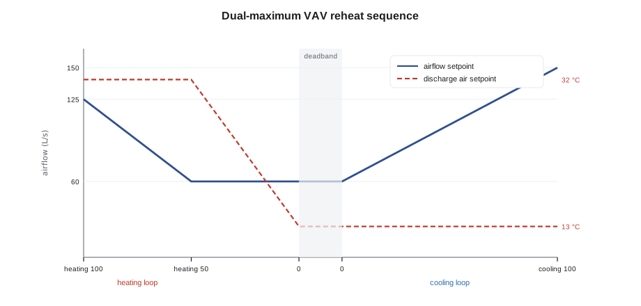
| Loop state | Single maximum (2009) | Dual maximum (draft) |
|---|---|---|
| Deadband | Minimum airflow, valve closed | Minimum airflow, valve closed |
| Heating 0 to 50 | Minimum airflow, valve opens on heating loop | Minimum airflow, discharge air setpoint rises, valve follows a discharge air loop |
| Heating 50 to 100 | Minimum airflow, valve continues to open | Discharge air at its maximum, airflow rises to the heating maximum |
| Cooling 0 to 100 | Airflow from minimum to cooling maximum | Airflow from minimum to cooling maximum |
The draft program
Sophie and Callie wrote the draft in structured text, following lessons 3, 5 and 10: a header with the sequence reference, named constants with their sources, sections in a clear order, and comments that explain why. The airflow values came from the 2009 balancing report, and the heating maximum was half the cooling maximum, a value Sophie would confirm against the coil's capacity before using it. The discharge temperature limit kept the warm air within a set rise above the room.
(* VAV-1-08  Tilden Hall room 108 : VAV with hot water reheat, dual maximum
   Sequence: Quillon draft TH-VAV-2027 rev A (S. Aubertin, Nov 2026)
   Airflows from the 2009 balancing report.                              *)
VAR CONSTANT
    VMIN     : REAL := 60.0;    (* L/s  occupied minimum                 *)
    VCOOLMAX : REAL := 150.0;   (* L/s  cooling maximum                  *)
    VHEATMAX : REAL := 125.0;   (* L/s  heating maximum                  *)
    DATMAXRISE : REAL := 11.0;  (* K above room: limit on warm air       *)
END_VAR

(* 1  airflow setpoint from the loops *)
IF OccMode = UNOCCUPIED THEN
    FlowSP := 0.0;
ELSIF CoolLoop > 0.0 THEN
    FlowSP := VMIN + CoolLoop / 100.0 * (VCOOLMAX - VMIN);
ELSIF HeatLoop > 50.0 THEN
    FlowSP := VMIN + (HeatLoop - 50.0) / 50.0 * (VHEATMAX - VMIN);
ELSE
    FlowSP := VMIN;
END_IF;

(* 2  discharge air setpoint for heating *)
IF HeatLoop > 0.0 THEN
    DATSP := LIMIT(AHUSupplyTemp,
                   AHUSupplyTemp + HeatLoop / 50.0 * (ZoneTemp + DATMAXRISE - AHUSupplyTemp),
                   ZoneTemp + DATMAXRISE);
END_IF;
The draft depended on one piece of hardware the 2009 box did not have: a discharge air temperature sensor after the reheat coil. Without it, the program could not hold a discharge air setpoint and could only open the valve on the heating loop, as before. Guideline 36's sequences assume one. Sophie wrote the sensor into the proposal, with a note that it would also have shown the stuck valve on November 12 at once, because the discharge air would have been warm while the valve was commanded shut.
Worked problem
Working through the draft
Room 108 is at 21 °C and the air handler supplies 13 °C air. With the draft's constants, what are the airflow setpoint and discharge air setpoint when the heating loop is at 25? At 75? What is the airflow setpoint when the cooling loop is at 40?
Show solution
- Maximum discharge temperature: 21 + 11 = 32 °C.
- Heating 25: airflow stays at VMIN, 60 L/s; DATSP = 13 + 25 ÷ 50 × (32 − 13) = 13 + 0.5 × 19 = 22.5 °C.
- Heating 75: DATSP is clamped at 32 °C; airflow = 60 + (75 − 50) ÷ 50 × (125 − 60) = 60 + 0.5 × 65 = 92.5 L/s.
- Cooling 40: airflow = 60 + 0.4 × (150 − 60) = 96 L/s.
Answer: At heating 25: 60 L/s at 22.5 °C. At heating 75: 92.5 L/s at 32 °C. At cooling 40: 96 L/s, the same as the old program, since cooling is unchanged.
Worked problem
Heating capacity at full heating
With the 32 °C maximum discharge temperature and the room at 21 °C, how much heat does the box deliver to the room at full heating in the old single-maximum sequence, at 60 L/s, and in the draft, at 125 L/s?
Show solution
- Single maximum: q ≈ 1.2 × 60 × (32 − 21) = 792 W.
- Dual maximum: q ≈ 1.2 × 125 × (32 − 21) = 1,650 W.
Answer: About 790 W against 1,650 W at the same discharge temperature limit. To match the draft with the old sequence, the discharge air would have to be much hotter, which is where stratification begins. For a cold perimeter room like 108, that is the main comfort gain.
Modes, loops and outputs
Around the two sections in the listing, the full draft had the other parts the course has covered. Lesson 7's occupancy logic chose occupied, standby or unoccupied from the schedule, the room sensor and the push-button override; in standby the setpoints relaxed and the minimum airflow could fall, as the sequence allowed. The cooling and heating loops were PI blocks configured as lesson 6 described: cooling direct and heating reverse, limits inside the blocks, enabled only when the air handler was proven, and tracking 0 when disabled. A damper airflow loop held measured airflow at FlowSP, and a discharge air loop drove the valve to hold DATSP. Every output was written in one place, and every mode set every output, as lesson 3's CASE table did.
Fault detection
The third section of the draft added what the old program lacked: rules that recognize when the box cannot do its job. Fault detection rules compare what should be happening with what is happening, for long enough to be sure. Guideline 36 includes such rules for terminal units, and BAS-330 covers fault detection and analytics across whole buildings. For VAV-1-08, Sophie wrote three to start with.
(* 3  fault rule: room too warm while the box is doing everything it can *)
HotFaultCond := (OccMode = OCCUPIED) AND (ZoneTemp > CoolSP + 2.0)
                AND (CoolLoop > 95.0) AND (FlowSP >= VCOOLMAX * 0.95)
                AND (HeatLoop < 1.0);
HotFaultDelay(IN := HotFaultCond, PT := T#60m);
ZoneHotFault := HotFaultDelay.Q; (* normal priority: check reheat valve *)| Fault rule | Condition held for a delay | Likely causes |
|---|---|---|
| Room too warm at full cooling | Occupied, room well above cooling setpoint, cooling loop and airflow at maximum, heating off | Reheat valve leaking or stuck open; supply air too warm; box undersized for the load |
| Discharge air warm with valve closed | Discharge air well above supply air temperature while the valve is commanded closed | Valve leaking or stuck open, as on November 12 |
| Airflow not following setpoint | Measured airflow far from setpoint for some minutes while the damper is at an end stop | Damper actuator slipped; low duct static; flow sensor fault |
The alarms from these rules would go to the normal priority class from lesson 9, routed to the front end and to Nell's work-order list, not to anyone's phone. They would be inhibited while the air handler was off and for an hour after warm-up, so that a cold Monday morning did not raise a dozen of them. Each would have a written response: what to check first, in what order.
Testing before anything changes
None of this would go into the box that week. Following lesson 11, Sophie planned to run the draft in simulation with a simple model of the room and coil, then on a bench controller with the new discharge sensor simulated by a decade box, then in one box in Tilden for a few weeks with trends of every point at a fast interval, before proposing it for the rest. The plan for the winter was a proposal to Gus in January 2027 covering the discharge sensors, the new program for Tilden's boxes and the fault rules, with the 14 forgotten overrides from lesson 11 released straight away as a no-cost first step.
As the workshop ended, Callie looked back over her notebook. In nine Saturdays and three weekdays she had learned to read a scan, follow a block page, trace a text program, build logic and timers, scale and guard values, configure loops, schedule a building, set up trends, design alarms, read a stranger's program and test it all before it touched a building. "The box is the smallest controller in the building," Sophie said, "and there are more of them than anything else. Get one right, copy it carefully, and test the copies. That's most of this job."
Common mistakes
MistakeProgramming a box to do more of the same when it cannot reach setpoint.
InsteadAdd fault rules that recognize when the box is at its limits and still failing, and alarm with a useful message.
MistakeHeating with very warm air at a minimum airflow.
InsteadLimit discharge temperature above room temperature and raise airflow for heating, as a dual-maximum sequence does.
MistakeWriting a discharge air sequence for a box with no discharge sensor.
InsteadAdd the sensor or keep the valve on the heating loop; the sequence must match the hardware.
MistakeCopying a new box program to every box at once.
InsteadTest in simulation, on the bench and in one box with fast trends before copying.
MistakeLeaving magic numbers in a new program.
InsteadName every constant and record its source, such as the balancing report.
Summary and key terms
- A stuck-open reheat valve can leave a room hot while the program believes it is cooling at full capacity.
- Single-maximum reheat heats at minimum airflow with hot discharge air; dual-maximum raises discharge temperature first, then airflow.
- Guideline 36 describes dual-maximum VAV reheat sequences and fault rules; it assumes a discharge air sensor.
- The draft program used named constants, a clamped discharge setpoint and an airflow setpoint from the loops.
- Air heat can be estimated as about 1.2 × L/s × ΔT in watts.
- Fault rules compare what should happen with what does, over a delay, and route useful alarms.
- New programs are proved in simulation, on the bench and in one unit before they are copied.
- VAV box
- A terminal unit that varies the airflow to a zone, often with a reheat coil.
- Single-maximum sequence
- VAV reheat in which heating is done at the minimum airflow.
- Dual-maximum sequence
- VAV reheat in which discharge temperature rises first and then airflow rises to a heating maximum.
- Heating maximum
- The highest airflow a box uses in heating in a dual-maximum sequence.
- Discharge air temperature
- The temperature of air leaving a terminal unit after its reheat coil.
- Stratification
- Warm air collecting near the ceiling instead of mixing into a room.
- Fault rule
- Logic that recognizes when equipment cannot do its job, based on conditions held for a delay.
- ASHRAE Guideline 36
- A guideline of high-performance sequences of operation for HVAC systems.
Practice problems
Work each problem on paper first, then reveal the answer to check.
Room 21 °C, supply 13 °C, maximum rise 11 K. What is DATSP at heating 50?
Show answer
13 + 1.0 × (32 − 13) = 32 °C.
With the draft's constants, what is the airflow setpoint at heating 100?
Show answer
125 L/s, the heating maximum.
Estimate the heat delivered by 100 L/s warmed 10 K.
Show answer
1.2 × 100 × 10 = 1,200 W.
Why did the draft need a discharge air sensor?
Show answer
To hold a discharge air setpoint and to see whether the valve is passing hot water.
Which fault rule would have caught the stuck valve fastest?
Show answer
Discharge air warm with the valve commanded closed.
Lesson quiz · 5 questions
Score 60% or more to complete this lesson.
Create a free account to save your progress, take quizzes and earn a certificate.