
BAS-120 · Lesson 2 of 12 · 23 min
Temperature sensors: thermistors, RTDs and thermocouples
▶ Video coming soon A video version of this lesson is on the way.
On Wednesday, September 16, Gus Thibodeaux called Quillon about Tilden Hall's outdoor air temperature. A summer contractor had replaced the sensor on the north wall after a ladder knocked it off, and since then the reading had seemed a degree or so warm in the cool mornings. It was a small error, but Tilden's hot water reset, its economizer and its freeze protection all used that one reading. Prakash brought Callie, a reference thermometer and the original submittal for the sensors. Within half an hour they knew what was wrong, and it had nothing to do with where the sensor was mounted.
Temperature is the most measured quantity in any building. This lesson explains the three kinds of temperature sensor a controls technician meets: thermistors, which are by far the most common in building automation; resistance temperature detectors, or RTDs, which are used where better accuracy or stability is needed; and thermocouples, which are common in boilers and industrial processes but rare in HVAC controls. It also covers sensor packages, where to mount them, and how to check one with a meter.
Thermistors
A thermistor is a resistor made of a semiconducting ceramic whose resistance changes strongly with temperature. Building automation uses negative temperature coefficient (NTC) thermistors, whose resistance falls as temperature rises. The standard building automation thermistor has a resistance of 10,000 ohms at 25 °C (77 °F), and is called a 10K thermistor. Its resistance roughly doubles for every 15 degrees Celsius of cooling and halves for a similar rise, so the change per degree is large: around 500 ohms per degree Celsius near room temperature. That large signal is the thermistor's great advantage. The resistance of the wires between the sensor and the controller is a few ohms at most and makes no practical difference.
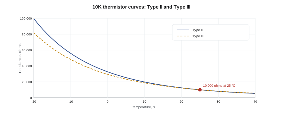
The catch is that thermistors are not all alike. Manufacturers make 10K thermistors with different curves, meaning different resistances at every temperature except 25 °C, where they all read 10,000 ohms. The two curves seen most in North American buildings are usually called Type II and Type III. Other controllers use 3K, 20K or 100K thermistors, or their own proprietary curves. A controller input must be configured for the exact curve of the sensor wired to it. A Type III sensor read as a Type II will be right at 25 °C and increasingly wrong as the temperature moves away from it.
| Temperature | 10K Type II (typical) | 10K Type III (typical) |
|---|---|---|
| −10 °C | about 55,800 Ω | about 48,100 Ω |
| 0 °C | about 32,650 Ω | about 29,490 Ω |
| 22 °C | about 11,400 Ω | about 11,280 Ω |
| 25 °C | 10,000 Ω | 10,000 Ω |
What had happened at Tilden
The original submittal showed that Tilden's controllers used 10K Type II sensors. The replacement on the north wall was a perfectly good outdoor sensor from another manufacturer, but its label said 10K Type III. With the reference thermometer reading 16.2 °C beside the sensor, Callie disconnected one lead and measured about 14,300 ohms, which matched the Type III table, not the Type II. The controller, reading that resistance on the Type II curve, reported about 16.9 °C. An error of under a degree on a mild morning would grow as winter came.
Worked problem
How big would the error be in winter?
At a true outdoor temperature of 0 °C, a 10K Type III sensor reads about 29,490 Ω. What temperature does a controller configured for Type II report? And at a true −10 °C?
Show solution
- On the Type II curve, 29,490 Ω falls between 0 °C (32,650 Ω) and about 3 °C; working the curve through gives about 2.0 °C.
- At −10 °C the Type III sensor reads about 48,100 Ω, which the Type II curve reports as about −7.3 °C.
- The error grows from about 2.0 K at 0 °C to about 2.7 K at −10 °C.
Answer: In the coldest weather the controller would think it was several degrees warmer than it was. The hot water reset would run the loop cooler than designed, and the freeze protection logic would act later than intended.
Prakash ordered a Type II outdoor sensor to match the rest of the building, and in the meantime Callie changed that one input's configuration to Type III so that the reading was right straight away. She noted both changes on the point list, so that whoever replaced the temporary arrangement would know to change the input back. "The curve has to match on both ends," Prakash said. "Write it on the point list and on the inside of the panel door."
Resistance temperature detectors (RTDs)
An RTD is a sensor made of a fine metal wire or film whose resistance rises in a nearly straight line with temperature. The most common is platinum. A platinum RTD is described by its resistance at 0 °C, usually 100 ohms (Pt100) or 1,000 ohms (Pt1000), and by its temperature coefficient, usually 0.00385 per degree Celsius, which means its resistance rises by 0.385 in 100 of that value for each degree Celsius. Building automation more often uses Pt1000 sensors, because the larger resistance makes wire resistance less important. Some older systems use nickel or Balco (a nickel-iron alloy) RTDs of 1,000 ohms, which have their own curves.
RTDs are more accurate, more stable over years and more nearly linear than thermistors, which is why they are specified for chilled water and hot water supply and return temperatures used in energy calculations, and in laboratories and hospitals. Their weakness is that the change per degree is small: a Pt1000 changes by only 3.85 ohms per degree Celsius, about one hundredth of a thermistor's change. Wire resistance therefore matters.
Worked problem
Lead wire error on a two-wire RTD
A Pt1000 RTD with a coefficient of 0.00385 measures a chilled water return. What does it read at 22 °C, and how much error do 30 m of 18 AWG copper each way add on a two-wire connection? Take 18 AWG copper as 0.021 Ω per metre.
Show solution
- At 22 °C: 1,000 × (1 + 0.00385 × 22) = 1,084.7 Ω.
- Lead resistance: 60 m × 0.021 = 1.26 Ω, added to the sensor's resistance.
- Error: 1.26 ÷ 3.85 Ω per K = about 0.33 K, reading high.
Answer: About 0.3 K. For a thermistor the same wire would add an error of a few thousandths of a degree. For an RTD the fix is a three-wire or four-wire connection, or an offset entered after checking against a reference.
Three-wire RTDs add a third conductor so that the controller or transmitter can measure the lead resistance and subtract it. Four-wire RTDs, used in laboratory and calibration work, eliminate it completely. Many building controllers accept only two-wire RTDs, so long runs to Pt1000 sensors are often handled with an RTD transmitter mounted near the sensor that converts the reading to 4 to 20 mA.
Thermocouples
A thermocouple is a junction of two different metals that produces a tiny voltage, a few millivolts, that depends on the temperature difference between the measuring junction and the cold end where the wires connect to the instrument. Thermocouples work at very high temperatures, which is why they are used in flue gas and combustion measurements, furnaces and industrial processes, and as the flame-proving device on standing-pilot gas appliances. They are rare in building automation because their signal is small, they need special extension wire and cold-junction compensation, and they are less accurate than thermistors and RTDs at room temperatures. When a building controller needs a thermocouple reading, such as a boiler stack temperature, it usually comes through a transmitter that converts it to 4 to 20 mA.
| Sensor | Signal | Typical use in buildings | Strengths | Weaknesses |
|---|---|---|---|---|
| 10K thermistor | Large resistance change, non-linear | Room, duct, outdoor and most water temperatures | Cheap, big signal, wire resistance negligible | Curve must match the controller; less stable at extremes |
| Pt1000 RTD | Small, nearly linear resistance change | Water temperatures for energy metering, critical spaces | Accurate, stable, interchangeable | Wire resistance matters; costs more |
| Thermocouple | A few millivolts | Flue gas, combustion, high-temperature processes | Very wide range, rugged | Needs a transmitter and special wire; less accurate at room temperature |
Sensor packages and where to mount them
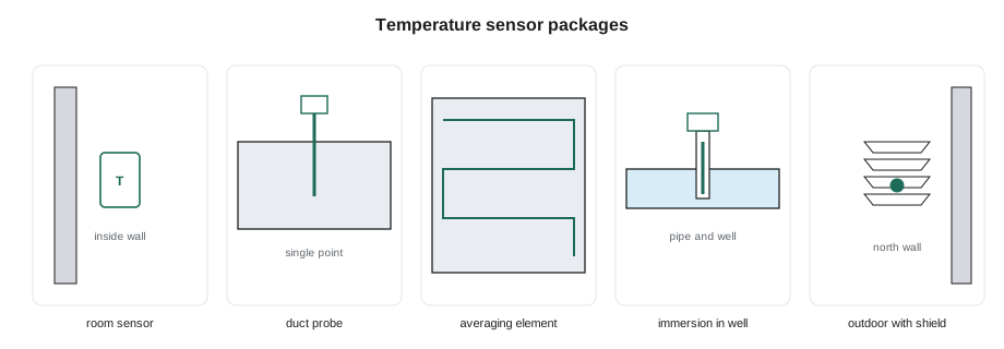
The sensing element is only part of the story. The same thermistor can be packaged as a room sensor, a duct probe, an averaging element, a strap-on pipe sensor, an immersion sensor in a thermowell, or an outdoor sensor with a sun shield. The package determines what temperature the element actually feels, and a well-chosen element in the wrong package or place gives a precise reading of the wrong thing.
- Room sensors belong on an inside wall, about 1.5 m above the floor, away from supply air diffusers, sunlight, lights, computers, coffee makers and outside walls. The hole behind the sensor should be sealed so that air from the wall cavity does not blow across the element.
- Duct probes measure at a single point a short way into the duct, and suit supply air downstream of a fan where the air is well mixed.
- Averaging sensors have a long flexible element, or a string of thermistors, strung back and forth across the face of a coil or mixing plenum. They are used for mixed air and coil discharge temperatures, where air streams at different temperatures have not yet mixed. Lesson 12 shows how the element length is chosen.
- Immersion sensors sit in a thermowell, a closed metal tube screwed into the pipe, so that the sensor can be removed without draining the system. A little heat-conducting compound in the well speeds the response.
- Strap-on sensors clamp to the outside of a pipe under insulation. They are cheap and easy to retrofit but read lower on hot pipes and higher on cold pipes than an immersion sensor, and they respond slowly.
- Outdoor sensors need a radiation shield and a north-facing wall, away from exhaust air, windows, dryer vents and roof surfaces. A sensor in the sun can read many degrees high.
Checking a temperature sensor
The quickest check is to compare the reading with a trusted reference thermometer placed beside the element. If the two disagree, disconnect one lead of the sensor at the controller and measure its resistance, then look up that resistance in the manufacturer's table for the sensor type. If the resistance matches the reference temperature, the sensor is good and the problem is in the controller's configuration or wiring. If it does not, the sensor has drifted or failed, or it is a different type from what the documents say. An open circuit reads as infinite resistance, which a thermistor input shows as a very low temperature; a short circuit reads as near zero resistance, which shows as a very high temperature. Many controllers report those readings as faults. Lesson 10 covers calibration and reference instruments in more depth.
Response time and self-heating
Two smaller effects explain many puzzling temperature readings. The first is response time. A sensor takes time to reach the temperature around it, and the time depends far more on the package than on the element. A bare thermistor bead in moving air responds within seconds; the same bead inside a stainless probe, a thermowell or a plastic room sensor cover may take several minutes to settle after a change. A slow sensor makes a control loop sluggish and can make it hunt, because the controller keeps acting on old information. When a loop seems unstable, check how the sensor is mounted before blaming the tuning, which BAS-130 covers.
The second is self-heating. A controller measures a resistance by passing a small current through it, and that current warms the element slightly. Building controllers keep the current small enough that the effect is a few hundredths of a degree for a thermistor. It becomes noticeable only when someone wires a sensor to an input meant for a different type, or uses a meter or test instrument that drives a larger current through a small sensor. It is one more reason to use the input type the manufacturer specifies.
At Tilden, Callie also checked the response of the new outdoor sensor by holding the reference probe and the sensor in the shade of the shield together for ten minutes. The two readings tracked each other once the curve setting was corrected, which showed that the sensor's package and shield were fine. The only problem had been the curve.
Common mistakes
MistakeReplacing a thermistor with any 10K sensor that is to hand.
InsteadMatch the curve type, or change the controller's input configuration and record the change.
MistakeMounting a room sensor on an outside wall or above a printer.
InsteadUse an inside wall away from heat sources and drafts, and seal the hole behind it.
MistakeUsing a single-point probe for mixed air.
InsteadUse an averaging element across the plenum or coil face.
MistakeRunning a two-wire RTD a long way without allowing for the leads.
InsteadUse a three-wire RTD, a transmitter, or an offset checked against a reference.
MistakeUsing a strap-on sensor where accuracy matters.
InsteadUse an immersion sensor in a thermowell for energy metering and critical loops.
MistakeLeaving an outdoor sensor in the sun.
InsteadMount it on a north wall under a radiation shield.
Summary and key terms
- NTC thermistors are the most common building sensors; 10K thermistors read 10,000 Ω at 25 °C and change about 500 Ω per degree Celsius near room temperature.
- Different 10K curves, such as Type II and Type III, agree only at 25 °C; the controller input must match the sensor.
- Platinum RTDs such as Pt1000 change in a nearly straight line, about 3.85 Ω per degree Celsius, so wire resistance matters.
- Thermocouples produce millivolts and are used for high temperatures, usually through a transmitter.
- The sensor package and location decide what the sensor actually measures.
- Check a sensor against a reference, then by its resistance against the manufacturer's table.
- Thermistor
- A semiconductor resistor whose resistance changes strongly with temperature.
- NTC
- Negative temperature coefficient: resistance falls as temperature rises.
- Thermistor curve
- The table of resistance against temperature for a particular thermistor type.
- RTD
- Resistance temperature detector: a metal element whose resistance rises nearly linearly with temperature.
- Pt1000
- A platinum RTD with 1,000 Ω at 0 °C.
- Thermocouple
- A junction of two metals producing a small voltage that depends on temperature.
- Thermowell
- A closed tube in a pipe that holds an immersion sensor.
- Averaging sensor
- A long sensing element strung across a duct or coil to read the average temperature.
Practice problems
Work each problem on paper first, then reveal the answer to check.
What does a 10K thermistor read at 25 °C, whatever its curve?
Show answer
10,000 Ω.
Why does lead resistance matter more for an RTD than for a thermistor?
Show answer
An RTD changes only a few ohms per degree, so a few ohms of wire is a noticeable error; a thermistor changes hundreds of ohms per degree.
A thermistor input suddenly shows a very low temperature. What two causes should you check first?
Show answer
An open circuit, such as a broken wire or loose terminal, or a failed sensor.
Where should an outdoor air sensor be mounted?
Show answer
On a north wall under a radiation shield, away from exhausts, windows and roofs.
Why use a thermowell?
Show answer
So the immersion sensor can be removed without draining the pipe.
Lesson quiz · 5 questions
Score 60% or more to complete this lesson.
Create a free account to save your progress, take quizzes and earn a certificate.