
BAS-120 · Lesson 1 of 12 · 24 min
Analog and digital signals in controls
▶ Video coming soon A video version of this lesson is on the way.
On Wednesday, September 9, her second day at Quillon Building Controls, Callie Rintoul sat with Prakash Deshmukh in the Tilden Hall mechanical room at Harcastle College. The day before, he had shown her the front end and the alarm list. Today he handed her a printed point list for AHU-1, the classroom air handler, and a clipboard. "Every line on this sheet is a wire," he said. "Some carry a number, some carry a yes or a no, some go in and some go out. Before you can fix anything, you need to know which is which and what the signal on that wire should look like." They spent the morning walking from the controller panel to each device on the list and measuring what was on the terminals.
This course is about the devices at the ends of those wires: the sensors that tell a controller what is happening and the actuators, valves and relays that carry out its commands. This first lesson explains the kinds of signals that pass between field devices and controllers, how a controller turns an electrical signal into a reading in engineering units, and how to tell from a meter whether a signal makes sense. BAS-110 introduced point types; here they become volts, milliamps and ohms. Later lessons look at each family of device in turn, and BAS-210 covers the controller end of the wiring in depth.
Inputs and outputs, analog and binary
A controller has inputs, which bring information in, and outputs, which send commands out. Each can be analog, meaning it can take any value across a range, or binary, meaning it is either on or off. Combining the two gives the four basic point types that appear on every point list: analog input (AI), analog output (AO), binary input (BI) and binary output (BO). BACnet, the most common building automation protocol, uses these same names, and many manufacturers also call binary points digital inputs and digital outputs (DI and DO). The words mean the same thing.
| Point type | Direction | What it carries | Typical examples |
|---|---|---|---|
| Analog input (AI) | Field to controller | A measured value across a range | Temperature, pressure, humidity, flow, CO2 |
| Binary input (BI) | Field to controller | An open or closed contact | Fan status, filter switch, freezestat, alarm contact |
| Analog output (AO) | Controller to field | A command across a range | Valve position, damper position, drive speed |
| Binary output (BO) | Controller to field | An on or off command | Fan start, pump start, enable a boiler |
On AHU-1's point list, the supply air temperature was an AI, the supply fan status was a BI, the heating valve was an AO and the supply fan start was a BO. Callie also found a few points marked AV and BV. Prakash explained that these are analog and binary values that live inside the controller, such as a setpoint or a calculated mixed air fraction, with no wire attached. They appear in the front end like real points, which is why technicians sometimes go looking for a sensor that does not exist.
What an analog signal is
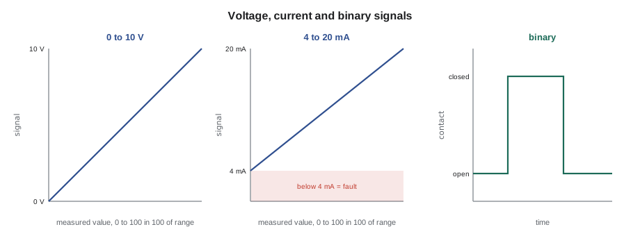
An analog signal represents a measured or commanded quantity by an electrical value that changes smoothly with it. A duct pressure transmitter might send 0 volts at no pressure and 10 volts at full scale, with every pressure in between represented by a voltage in between. The controller's input circuit reads the voltage, converts it to a number with an analog-to-digital converter, and scales that number into engineering units such as pascals or inches of water column. The signal itself has no meaning until the controller knows its range.
Three kinds of analog signal are common in building controls. Voltage signals, usually 0 to 10 volts DC or 2 to 10 volts DC, are simple and cheap. Current signals, almost always 4 to 20 milliamps DC, hold up better over long wire runs and in electrically noisy places. Resistive signals come from sensors whose resistance changes with what they measure, mainly thermistors and RTDs for temperature; the controller supplies a small current and reads the resistance directly. Lesson 9 covers the wiring of each kind, and lesson 2 explains the resistive temperature sensors.
Live zero: why 4 to 20 mA starts at 4
A 4 to 20 milliamp signal represents the bottom of its range with 4 milliamps, not with zero. This is called a live zero. If the wire breaks, the transmitter loses power or a terminal comes loose, the current drops to zero, which is below the bottom of the range and therefore cannot be a real reading. The controller can flag the input as failed instead of reporting a pressure of zero and letting a fan ramp up to chase it. The 2 to 10 volt signal has the same advantage over 0 to 10 volts: a reading near 0 volts on a 2 to 10 volt input means a fault.
The live zero has a second benefit for current loops. A two-wire 4 to 20 mA transmitter takes its own operating power from the loop current, so it needs the 4 milliamps at the bottom of the range just to keep its electronics running. That is why most pressure and humidity transmitters in buildings can be wired with only two conductors. Lesson 9 shows how to check that a loop has enough voltage to drive the transmitter to 20 mA.
Scaling a signal into engineering units
Every analog input has a range that the controller must be told: the signal value at the bottom of the measuring range and the value at the top. The conversion between them is a straight line for most transmitters, so any reading can be worked out by proportion. A technician who can do this in their head can check a reading against a meter in seconds.
Worked problem
Scaling a 4 to 20 mA duct pressure transmitter
AHU-1's duct static pressure transmitter is ranged 0 to 500 Pa with a 4 to 20 mA output. Callie measures 9.6 mA in the loop. What pressure should the front end show?
Show solution
- Span of the signal: 20 − 4 = 16 mA.
- Fraction of span: (9.6 − 4) ÷ 16 = 0.35.
- Pressure: 0 + 0.35 × 500 = 175 Pa.
Answer: The front end should read 175 Pa. If it shows something else, the range in the controller or the transmitter setting is wrong.
That morning the front end showed 175 Pa, which matched. Prakash told Callie about a job years earlier where a replacement transmitter had been set to a different range from the one in the controller. The reading looked reasonable, so nobody questioned it, but the fan was holding a pressure 40 in 100 higher than the design. Matching the transmitter's range setting to the controller's range is one of the first checks after any sensor replacement.
Resolution: how fine a reading can be
A controller's analog-to-digital converter divides its input range into a fixed number of steps. A 10-bit converter has 1,024 steps, a 12-bit converter 4,096 and a 16-bit converter 65,536. The smallest change the controller can see is the measuring range divided by the number of steps. For most building measurements, a 12-bit input is fine enough that resolution is not the limit; the sensor's own accuracy matters far more.
Worked problem
Resolution of a voltage input
A 0 to 10 V temperature transmitter covers 0 to 50 °C. How fine is the reading on a 12-bit input, and on an older 10-bit input?
Show solution
- 12-bit: 10 V ÷ 4,096 = about 2.44 mV per step, and 50 K ÷ 4,096 = about 0.012 K per step.
- 10-bit: 50 K ÷ 1,024 = about 0.049 K per step.
Answer: Both are far finer than the sensor's typical accuracy of a few tenths of a degree, so resolution is not the weak point here.
Resolution becomes a problem when a wide-range transmitter is used to measure something small. A pressure transmitter ranged for several thousand pascals, used to measure a building pressure of a few pascals, may not resolve the reading at all. Choosing a sensor whose range suits the measurement is the fix, and lesson 3 returns to it.
Binary inputs: contacts and their states
A binary input senses whether a contact is open or closed. The controller usually supplies a small voltage across the input and detects whether current flows. The device in the field is a dry contact, meaning a switch with no voltage of its own: the auxiliary contact on a motor starter, a current switch, a differential pressure switch on a filter or a freezestat contact. Applying an outside voltage to a dry-contact input can damage it, which is why controls technicians check the device and the input type before landing a wire.
Every binary input also has a normal state, and a contact can be normally open (NO) or normally closed (NC). The choice matters for safety. A freezestat or a smoke detector relay is usually wired so that the contact is closed when all is well and opens on alarm. A broken wire then looks the same as an alarm, so the system fails safe. A fan status switch is usually normally open and closes when the fan runs. The point list should say which, and the controller's configuration must match the wiring.
| Device | Usual contact | Closed means | Why |
|---|---|---|---|
| Fan status (current switch) | Normally open | Fan running | Proves the fan is moving air |
| Filter differential pressure switch | Normally open | Filter dirty | Alarm only; no safety function |
| Freezestat (low limit) | Normally closed | Coil air safe | A break in the wire shuts the unit down safely |
| Smoke detector relay | Normally closed | No smoke | Fails safe on a broken wire |
| Motor starter auxiliary | Normally open | Starter energized | Shows the command was obeyed, not that the fan turns |
Analog outputs and what they drive
An analog output produces a voltage or current that commands a device to a position or speed. Most valve and damper actuators in buildings take 0 to 10 or 2 to 10 volts DC; variable frequency drives take 0 to 10 V or 4 to 20 mA. The controller's output scaling maps 0 to 100 in 100 of command onto the signal range. On AHU-1, the heating valve output was commanded to 38 in 100 and configured in the controller as a 2 to 10 V output. Callie worked out the expected signal first: 2 V plus 0.38 of the 8-volt span is 5.04 volts. Her meter read 5.0 volts, so the controller was doing its job. But the position indicator on the valve showed it about half open, not 38 in 100. Prakash had her read the label on the actuator: its selector switch was set to 0 to 10 V, so it treated 5.0 volts as 50 in 100 of travel. Someone had changed the switch years earlier, and the controller had never been told. At the bottom of the range the mismatch was worse: a 0 command sent 2 volts, which held the valve 20 in 100 open, so the coil was never fully off.
The lesson was that a measurement only makes sense when you know what range the device expects. Callie set the actuator's switch back to 2 to 10 V to match the drawings and the controller, then stroked the valve from 0 to 100 in 100 and watched the indicator follow the command. The heating valve now closed fully at a 0 command. Lesson 6 explains actuators and their signal settings in more detail.
Binary outputs and the relay between
A binary output turns a device on or off. Controller binary outputs are usually small relays or triacs that can switch 24 volts AC at a fraction of an amp. They are not meant to switch a 600-volt fan motor directly. Instead, a binary output energizes the coil of an interposing relay or the control circuit of a motor starter, which in turn switches the larger load. Lesson 8 explains relays, contactors and the current switches that prove a motor is really running.
Callie traced AHU-1's supply fan start from the controller's BO to a small relay in the panel, and from the relay's contact to the hand-off-auto switch in the drive's control circuit. The point list said the fan status came from a current switch on the motor leads. That pair, a command and a separate proof, is the pattern for every motor in a building: the controller should never assume that a command was obeyed.
Reading a signal with a meter
The basic tools for checking signals are a digital multimeter that can read DC volts, DC milliamps and ohms, and the device's documentation. Voltage is read across the input terminals with the circuit live. Current is read either by breaking the loop and putting the meter in series, or with a milliamp clamp meter that reads loop current without opening the circuit. Resistance is read only with the sensor disconnected from the controller, because the controller's own measuring current upsets the meter.
Prakash's habit, which he passed to Callie that day, was to write the expected value on the point list before measuring, then the measured value beside it. "If you measure first and decide afterwards whether it looks right, you'll talk yourself into anything," he said. ELEC-110 covered meter use and safety; the controls version of that rule is to know the range, work out the expected signal, and only then put the probes on.
Common mistakes
MistakeAssuming a 0 to 10 V signal when the device is set to 2 to 10 V, or the reverse.
InsteadCheck the device's range setting and the controller's configuration, and make them match.
MistakeMeasuring resistance on a sensor still connected to a controller input.
InsteadDisconnect one lead first; the controller's measuring current makes the ohmmeter reading wrong.
MistakeTreating 0 mA on a 4 to 20 mA input as a real zero reading.
InsteadAnything well below 4 mA is a fault: an open loop, a dead transmitter or a loose terminal.
MistakeSwitching a motor directly from a controller binary output.
InsteadUse an interposing relay or the starter's control circuit.
MistakeTrusting a motor start command as proof that the motor runs.
InsteadUse a separate status input such as a current switch or airflow switch.
MistakeLooking for a wire on a virtual point.
InsteadAV and BV points live in the controller and have no field device.
Summary and key terms
- Controllers have analog and binary inputs and outputs: AI, AO, BI and BO.
- Analog signals are usually 0 to 10 V, 2 to 10 V, 4 to 20 mA or a resistance.
- A live zero at 2 V or 4 mA lets the controller detect a broken wire or a dead transmitter.
- Scaling is a straight-line proportion between the signal range and the measuring range.
- Resolution is the range divided by the converter's steps; sensor accuracy usually matters more.
- Binary inputs read dry contacts; safeties are usually wired normally closed so they fail safe.
- Binary outputs drive relays or starter circuits, never large motors directly.
- Work out the expected signal before you measure it.
- Analog input (AI)
- A controller input that reads a value across a range.
- Binary input (BI)
- A controller input that reads an open or closed contact.
- Analog output (AO)
- A controller output that commands a position or speed across a range.
- Binary output (BO)
- A controller output that commands a device on or off.
- Live zero
- A signal range that starts above zero, such as 4 mA or 2 V, so that a fault can be told from a real low reading.
- Scaling
- Converting a signal value into engineering units using the signal and measuring ranges.
- Resolution
- The smallest change an input can detect: the range divided by the converter's number of steps.
- Dry contact
- A switch contact with no voltage of its own, read by a binary input.
Practice problems
Work each problem on paper first, then reveal the answer to check.
A 4 to 20 mA humidity transmitter covers 0 to 100 RH. It reads 12 mA. What humidity is that?
Show answer
(12 − 4) ÷ 16 = 0.5 of span, so 50 in 100 RH.
A 2 to 10 V input reads 0.3 V. What does that suggest?
Show answer
A fault, such as an open wire or a failed sensor, because the live zero is 2 V.
Why are freezestat contacts normally closed?
Show answer
So that a broken wire or loose terminal shuts the unit down, the same as a real alarm.
What is an AV point?
Show answer
An analog value stored in the controller, such as a setpoint, with no field wiring.
What does a 12-bit converter divide its range into?
Show answer
4,096 steps.
Lesson quiz · 5 questions
Score 60% or more to complete this lesson.
Create a free account to save your progress, take quizzes and earn a certificate.