
AUTO-230 · Lesson 4 of 12 · 20 min
Engine sensors for fuel control
Harold Kemp's luxury SUV, back on its repaired air suspension since last term, has a new problem. It hesitates when he pulls out into traffic, feels flat on the highway on-ramp, and the check-engine lamp has come on with P0101, mass air flow sensor circuit range or performance. Harold mentions, with some pride, that he fitted a washable high-flow air filter over the winter, oiled it himself, and that the SUV has never felt the same since, which he blames on the cold. Kiran writes that down. Marty tells her the code tells her which sensor the computer distrusts, not which part is broken. "The computer compares sensors with each other," he says. "Find out what it was comparing."
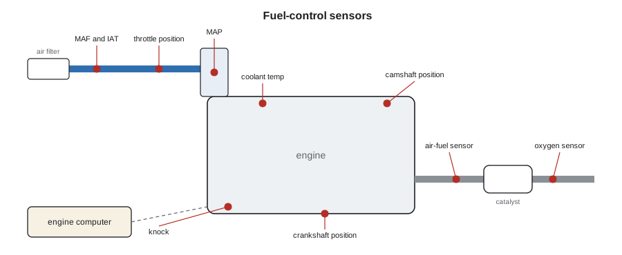
This lesson covers the sensors the engine computer uses to decide how much fuel to inject and when: the mass airflow and manifold pressure sensors that measure the air, the temperature sensors that correct for it, the throttle and pedal sensors, the crankshaft and camshaft sensors that time everything, the knock sensor, and the oxygen and air-fuel sensors that check the result. AUTO-220 covered how sensor circuits work electrically; this lesson covers what each one measures and how its readings are judged.
Measuring the air: mass airflow
Fuel must match the mass of air in the cylinder, so the most important input is the one that measures air. Most engines use a mass airflow (MAF) sensor in the intake duct between the air filter and the throttle body. A hot-film MAF sensor has a heated element in a small sample passage; the electronics keep the element a fixed amount hotter than the incoming air, and the current needed to do that rises with the mass of air flowing past, because more air carries away more heat. Because it measures cooling, a hot-film sensor responds to air mass directly and automatically corrects for altitude and temperature. Its output is either an analogue voltage, typically about 1 volt at idle rising toward 4 or 5 volts at full load, or, on many newer engines, a frequency that rises with airflow. The scan tool shows the computer's interpretation in grams per second.
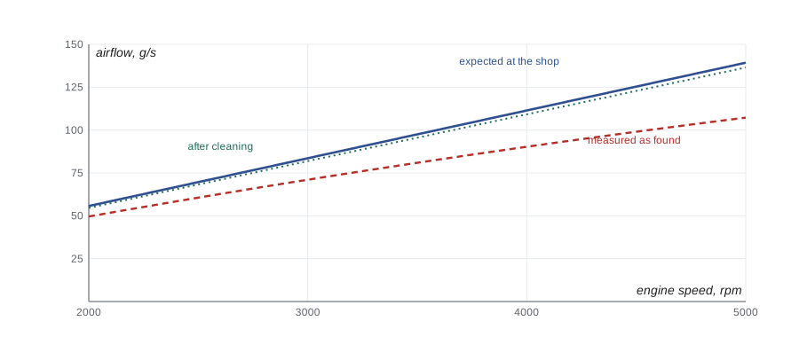
A useful rule of thumb is that a warm engine at idle at sea level draws roughly one gram per second of air for every litre of displacement, and at full throttle draws a mass that can be calculated from displacement, engine speed, volumetric efficiency and air density. At Calgary's altitude, both figures are about 12 percent lower. A MAF sensor that is contaminated with oil, dirt or debris usually reads low, because the coating insulates the element, and the effect is greatest at high airflow. The engine runs lean under load, the computer adds fuel through its long-term trim, and the trims are higher at high load than at idle, which is one of the patterns Lesson 5 teaches.
In the equation, ṁ is the air mass flow in grams per second, V_d is displacement in litres, n is engine speed in rpm, η_v is volumetric efficiency, about 0.80 to 0.90 at full throttle on a healthy naturally aspirated engine, and ρ is air density in kilograms per cubic metre. The factor of 120 converts rpm to cycles per second for a four-stroke engine, which fills each cylinder once every two revolutions.
# Expected mass airflow at wide-open throttle compared with the scan tool reading
R = 287.0
def density(p_kpa, t_c):
    return p_kpa * 1000 / (R * (t_c + 273.15))
displacement = 3.6           # L
ve = 0.85                    # volumetric efficiency at full throttle
baro = 89.4 * 1.0          # barometric pressure at the shop (read in kPa), converted for the density formula
rho = density(baro, 12)
for rpm, measured in ((2500, 59), (3500, 79), (4500, 99)):
    expected = displacement * rpm / 120 * ve * rho
    print(f"{rpm} rpm: expected {expected:5.1f} g/s, measured {measured:5.1f} g/s, {measured / expected * 100:4.0f} % of expected")
print(f"rule of thumb at idle: about {displacement * baro / 101.3:3.1f} g/s at this altitude")2500 rpm: expected 69.6 g/s, measured 59.0 g/s, 85 % of expected 3500 rpm: expected 97.5 g/s, measured 79.0 g/s, 81 % of expected 4500 rpm: expected 125.4 g/s, measured 99.0 g/s, 79 % of expected rule of thumb at idle: about 3.2 g/s at this altitude
Measuring the air: manifold pressure
The manifold absolute pressure (MAP) sensor measures the absolute pressure in the intake manifold, from near zero, a perfect vacuum, to atmospheric pressure or, on turbocharged engines, to boost. At idle a healthy engine pulls the manifold down to about 25 to 35 kPa (7 to 10 inHg absolute), and at wide-open throttle the reading rises to almost barometric pressure. With the key on and the engine off, the MAP sensor reads barometric pressure, and many computers store that as the baro reading for altitude correction; some engines have a separate barometric sensor. Technicians used to vacuum gauges should remember that vacuum is barometric pressure minus absolute pressure, so at altitude the same engine shows less vacuum on a gauge while the MAP reading looks normal.
Some engines have no MAF sensor and use the speed-density method instead: the computer calculates air mass from engine speed, manifold pressure, intake air temperature and a stored table of volumetric efficiency. Most engines with a MAF sensor still have a MAP sensor, and the computer cross-checks them. A MAF reading that does not agree with what manifold pressure, throttle position and engine speed predict is exactly what P0101 means: the computer's model of how much air should be flowing disagrees with the sensor.
Temperatures, throttle and pedal
The engine coolant temperature (ECT) sensor and intake air temperature (IAT) sensor are thermistors whose resistance falls as they get hotter, read by the computer through a pull-up resistor as AUTO-220 explained. Coolant temperature decides cold-start enrichment, idle speed and when closed-loop operation begins; a sensor that reads cold when the engine is warm makes the engine run rich, foul plugs and fail an emissions test. Intake air temperature corrects air density in speed-density calculations and spark timing for knock. A quick check is to compare the two readings with the key on after an overnight cold soak: they should agree with each other, and with the outside temperature, within a few degrees.
On electronic throttle control, sometimes called drive-by-wire, there is no cable between the pedal and the throttle. The accelerator pedal position (APP) sensor has two or three independent tracks, and the throttle body has a motor and two throttle position (TP) sensor tracks. The computer opens the throttle to match the driver's request and its own torque calculations, and it constantly compares each pair of tracks; if they disagree, it limits power and lights a warning, a mode technicians call limp-home or reduced power. A dirty throttle body, with carbon built up around the plate, can upset idle control, and many manufacturers require an idle relearn after cleaning.
Crankshaft, camshaft and knock sensors
The crankshaft position (CKP) sensor reads a toothed reluctor wheel on the crankshaft or flywheel, usually with a missing tooth or two as a reference. From it the computer knows engine speed and crankshaft angle to a fraction of a degree, and it watches for tiny changes in crankshaft speed between firing events, which is how misfires are detected, as Lesson 7 explains. The camshaft position (CMP) sensor reads a target on the camshaft, which turns at half crankshaft speed, so the computer can tell which stroke each cylinder is on and time sequential injection and coil-on-plug ignition; on engines with variable valve timing, the cam sensors also measure the actual cam angle. Older sensors are magnetic, generating an AC voltage that grows with speed; most are now Hall-effect or magnetoresistive sensors with a square-wave digital output.
A knock sensor is a piezoelectric accelerometer bolted to the block. When the end gas in a cylinder ignites spontaneously, the pressure wave rings the block at a characteristic frequency, and the sensor produces a small voltage at that frequency. The computer listens only in a window around each cylinder's firing, retards that cylinder's spark when knock is detected, and advances it again gradually. Knock sensors must be torqued to specification and their mounting faces must be clean, because a loose sensor cannot hear knock properly.
Oxygen and air-fuel sensors
A conventional oxygen sensor, also called a narrow-band or switching sensor, has a thimble of zirconium dioxide coated with platinum, with exhaust gas on the outside and outside air, the reference, on the inside. When the sensor is hot, above about 300 °C (570 °F), oxygen ions move through the ceramic and it generates a voltage that depends on the difference in oxygen between the two sides. With a rich exhaust, which has almost no free oxygen, the voltage is about 0.8 to 0.9 volts; with a lean exhaust it is about 0.1 volts; and it switches sharply between the two right at lambda 1. It tells the computer rich or lean, but not by how much. A built-in heater brings it to working temperature within seconds of a cold start. Narrow-band sensors are now used mainly after the catalyst, where they monitor it.
Before the catalyst, most newer engines use a wide-band air-fuel ratio sensor. It contains a sensing cell like a conventional sensor plus a pumping cell. The sensor's control circuit pumps oxygen ions into or out of a tiny measuring chamber to hold the sensing cell exactly at stoichiometric, and the pumping current needed to do so, positive for lean and negative for rich, tells the computer how far from lambda 1 the exhaust is. Scan tools show the result as lambda, as an equivalence ratio, as an air-fuel ratio, or as a current in milliamps; some manufacturers convert it to a voltage that rises when lean, the opposite of a conventional sensor. Technicians always check which convention the scan tool is using before deciding that a sensor reads rich or lean.
# Interpreting the two kinds of exhaust oxygen sensor (warm engine, closed loop)
def narrow_band(volts):
    if volts > 0.60: return "rich"
    if volts < 0.30: return "lean"
    return "crossing lambda 1"
def wide_band(lam):
    pct = (lam - 1) * 100
    return f"lambda {lam:4.2f}: {abs(pct):4.1f} % {'lean' if pct > 0 else 'rich' if pct < 0 else 'exact'}"
for v in (0.08, 0.45, 0.82):
    print(f"narrow-band {v:4.2f} V -> {narrow_band(v)}")
for lam in (0.97, 1.00, 1.04):
print("wide-band", wide_band(lam))narrow-band 0.08 V -> lean narrow-band 0.45 V -> crossing lambda 1 narrow-band 0.82 V -> rich wide-band lambda 0.97: 3.0 % rich wide-band lambda 1.00: 0.0 % exact wide-band lambda 1.04: 4.0 % lean
Harold's hesitation
Kiran starts with the scan data. At a warm idle the MAF reads 3.0 g/s, close to the 3.2 g/s the rule of thumb gives for a 3.6-litre engine at this altitude. Long-term fuel trims are +4 percent at idle but +16 percent at 2,500 rpm, a lean condition that grows with airflow. On a road test with full throttle in second gear, the MAF reads well below what the airflow calculation predicts, about 79 percent of expected at 4,500 rpm, while manifold pressure reaches baro and the throttle opens fully. Everything points to the MAF under-reading, and the question is why.
With the duct off, the answer is visible: the sensor's sample passage and element have a sticky film of red filter oil, and the inside of the duct is wet with it too. The over-oiled filter has been shedding oil into the airstream. Kiran explains to Harold through Simone that the oil insulates the sensing element, so the sensor reports less air than the engine is really breathing, and the engine runs lean under load. She cleans the sensor with the spray cleaner the manufacturer approves, never touching the element, cleans the duct, and fits a new paper filter of the original type. The trims settle at +2 percent at idle and +3 percent at 2,500 rpm, the full-throttle MAF reading rises to 98 percent of expected, and P0101 does not return after a drive cycle. Harold keeps his washable filter in a box in his garage.
Worked problem
Vacuum gauge or MAP sensor?
At Calgary, with the barometer at 89 kPa (26.3 inHg), an engine's MAP sensor reads 30 kPa (8.9 inHg) absolute at idle. What would a vacuum gauge on the manifold read, and what would it read at sea level with the same absolute pressure?
Show solution
- Vacuum = barometric pressure − absolute pressure.
- In the shop: 89 − 30 = 59 kPa of vacuum (26.3 − 8.9 = 17.4 inHg of vacuum).
- At sea level, barometric pressure is about 101 kPa (29.9 inHg).
- Vacuum there: 101 − 30 = 71 kPa (29.9 − 8.9 = 21.0 inHg).
Answer: About 59 kPa (17.4 inHg) in the shop, 71 kPa (21 inHg) at sea level: the engine is the same, only the air above it differs.
Common mistakes
MistakeReplacing a sensor because a code names it.
InsteadThe code names the sensor the computer distrusts; test it against the other sensors and against calculated values.
MistakeTouching or wiping a MAF sensing element.
InsteadUse only the approved spray cleaner, and never touch the element.
MistakeReading a wide-band sensor voltage as if it were a narrow-band sensor.
InsteadCheck the scan tool's convention: many wide-band displays rise when lean.
MistakeComparing vacuum gauge readings at altitude with sea-level specifications.
InsteadUse absolute pressure, or subtract from the local barometric pressure.
MistakeLeaving a knock sensor finger-tight after an intake job.
InsteadTorque it to specification on a clean mounting face.
Summary and key terms
- The engine computer meters fuel to the mass of air, measured by a MAF sensor or calculated from MAP.
- A contaminated MAF sensor usually reads low, with the error growing at high airflow.
- MAP reads absolute pressure; with the engine off it reads barometric pressure.
- ECT and IAT are thermistors; a cold-reading ECT makes an engine run rich.
- Drive-by-wire systems compare paired pedal and throttle sensor tracks and limit power if they disagree.
- Crank and cam sensors give speed, position and stroke; the crank signal also detects misfires.
- Narrow-band sensors switch at lambda 1; wide-band sensors report how far from lambda 1 the exhaust is.
- Mass airflow (MAF) sensor
- A sensor that measures the mass of air entering the engine by the cooling of a heated element.
- Manifold absolute pressure (MAP) sensor
- A sensor that measures absolute pressure in the intake manifold.
- Speed-density
- Calculating air mass from engine speed, manifold pressure, temperature and volumetric efficiency.
- Volumetric efficiency
- The ratio of air actually drawn into a cylinder to the cylinder's swept volume at ambient conditions.
- Knock sensor
- A piezoelectric sensor on the block that detects the vibration of abnormal combustion.
- Narrow-band oxygen sensor
- A sensor whose voltage switches sharply between rich and lean at lambda 1.
- Wide-band air-fuel sensor
- A sensor that uses a pumping cell to measure how far the mixture is from lambda 1.
Practice problems
Work each problem on paper first, then reveal the answer to check.
A 2.0-litre engine idles at sea level. Roughly what MAF reading is expected?
Show answer
About 2 g/s.
With the key on and engine off, the MAP sensor reads 89 kPa (26.3 inHg). What is it measuring?
Show answer
Barometric pressure.
A coolant sensor reads −20 °C (−4 °F) on a fully warm engine. How will the engine run?
Show answer
Rich, because the computer adds cold-start enrichment.
Long-term fuel trim is +3 percent at idle and +18 percent at 3,000 rpm. Which sensor is a good suspect?
Show answer
The MAF sensor, under-reading at high airflow.
Lesson quiz · 5 questions
Score 60% or more to complete this lesson.
Create a free account to save your progress, take quizzes and earn a certificate.