
AUTO-210 · Lesson 11 of 12 · 24 min
Performing a four-wheel alignment
Dr. Singh's electric hatchback is back on the rack in bay 3 with its new left rear toe link fitted and its new rear tires mounted. This is Kiran's first alignment from start to finish, with Marty beside her only to watch. Behind it in the queue is Ines Moreau's hybrid with its new front struts. “Every alignment is the same job in the same order,” Marty tells her. “The cars just give you different problems along the way.”
This lesson follows a four-wheel alignment step by step: the interview and road test, the pre-alignment inspection, setting the vehicle on the rack and compensating the measuring heads, reading the angles, and adjusting them in the correct order with the methods different suspensions use. It ends with the steps after the adjustment, steering angle sensor resets and driver assistance calibration checks, and with the printout and road test that finish the job.
Before the rack: interview and road test
An alignment starts with the customer. Simone has already noted Dr. Singh's concerns on the repair order: rear tires wearing on the inside, a steering wheel slightly off to the left, and a pothole hit in January. Kiran drives the car on the route Ridgeline uses for alignment road tests, a straight stretch of flat road with little crown, a few turns and a rough patch, and notes how it behaves: the steering wheel sits a few degrees left of centre when the car tracks straight, there is no pull, and the steering returns normally. A road test before the alignment confirms the complaint and sometimes finds a problem that an alignment will not cure, such as a tire pull or a dragging brake.
The pre-alignment inspection
No alignment is better than the parts it is set on, so the next step is a full inspection. Kiran sets all four tires to the placard pressure and checks that they are the correct size, matched across each axle, with similar tread depth. She measures the ride height at the points in the service information, because the specifications are given at ride height. She checks every steering and suspension part for play, as in Lessons 3, 4 and 6: ball joints, tie rod ends, inner tie rods, control arm and subframe bushings, strut mounts, wheel bearings and the steering gear's mounting. The vehicle's load is checked too: anything heavy in the cargo area that is not part of curb weight comes out, and the fuel tank, or on Dr. Singh's car the battery, is as the procedure states.
Any worn or damaged part is repaired before the alignment. If Kiran found a loose tie rod end now, setting the toe on top of it would be pointless, because the toe would wander as the joint moved. On Dr. Singh's car everything is tight, the new toe link is torqued at ride height, and the ride height is within specification.
# Pre-alignment checklist: everything must pass before adjusting
UNITS = "metric"
checks = [
    ("tire pressures set to placard", True),
    ("tire sizes match across each axle", True),
    ("tread depth difference across an axle within 2/32 or 1.5 mm", True),
    ("ride height within specification at all four corners", True),
    ("no play in ball joints, tie rods or wheel bearings", True),
    ("control arm and subframe bushings sound", True),
    ("steering gear mounting tight", True),
    ("cargo area empty, fuel or charge as specified", True),
]
failed = [name for name, ok in checks if not ok]
for name, ok in checks:
    print(f"[{'x' if ok else ' '}] {name}")
print("ready to align" if not failed else "repair first: " + ", ".join(failed))[x] tire pressures set to placard [x] tire sizes match across each axle [x] tread depth difference across an axle within 2/32 or 1.5 mm [x] ride height within specification at all four corners [x] no play in ball joints, tie rods or wheel bearings [x] control arm and subframe bushings sound [x] steering gear mounting tight [x] cargo area empty, fuel or charge as specified ready to align
Setting up on the rack
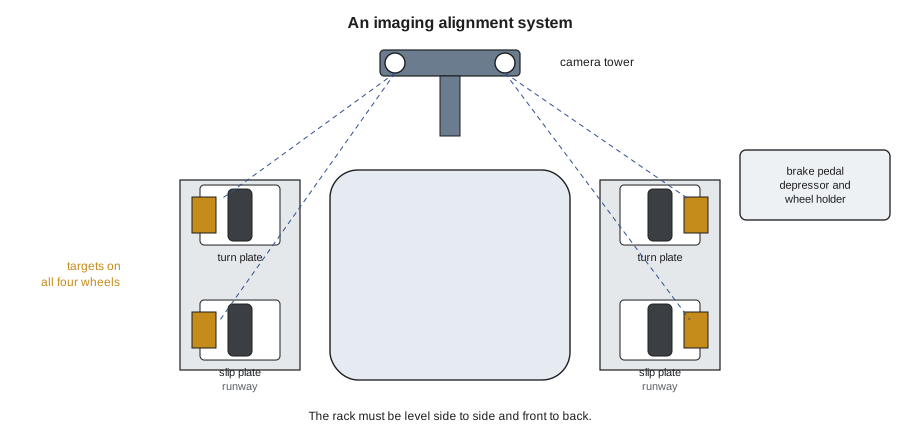
Ridgeline's alignment machine is an imaging system: cameras on a tower in front of the rack watch targets clamped to each wheel, and the computer calculates every angle from the targets' positions. Older machines use heads with sensors that clamp to the wheels and talk to each other across the vehicle. Both kinds need the same care. The rack must be level, because a rack that is out of level by even a small amount from side to side changes the camber readings; Dale has the rack's level checked as part of its regular maintenance. The front wheels sit on turn plates, which rotate and slide sideways, and the rear wheels on slip plates, so that the suspension can settle to its natural position as the vehicle is adjusted. The plates are locked with their pins while the vehicle is driven on, then unlocked.
Kiran drives the car onto the rack straight and centred, stops with the front tires in the middle of the turn plates, puts the car in park with the parking brake off so the rear wheels can move, and chocks nothing. She clamps the wheel adapters on, making sure their claws grip the rim's edge or the tire tread as the machine's maker specifies and do not touch wheel weights, and hangs the targets.
Next comes compensation. No wheel adapter mounts perfectly square to the wheel, and no wheel is perfectly flat, so the machine must learn how far each target wobbles as the wheel turns and subtract that wobble from its readings. On imaging systems this is usually rolling compensation: the vehicle is rolled backward a short distance and then forward again, and the cameras watch the targets rotate. On sensor heads, each wheel is raised and turned by hand through set positions. A bad compensation, because a target was bumped or a wheel slipped, gives bad readings, so the machine checks its result and Kiran redoes it if asked.
Reading the angles and the caster sweep
Once compensated, the machine shows the live rear camber, rear toe and thrust angle, the front camber and toe, and, after a caster sweep, the caster and steering axis inclination. For the sweep, Kiran fits a brake pedal depressor so that the wheels cannot roll, then follows the screen as she turns the steering wheel until the front wheels are about 10 or 20 degrees to one side, then the other, and back to centre. Caster cannot be measured with the wheels straight, because caster does not tilt a straight wheel, but as a wheel with positive caster is turned, its camber changes: the outside wheel gains negative camber and the inside wheel positive camber. The machine calculates the caster from that change.
# Caster from a caster sweep: the camber change as the wheel turns from 20 deg in to 20 deg out
import math
sweep = 20.0                                   # degrees each side of straight ahead
factor = 1 / (2 * math.sin(math.radians(sweep)))     # about 1.46 for a 20 degree sweep
for side, camber_in, camber_out in [("left front", 1.52, -2.71), ("right front", 1.66, -2.85)]:
    caster = (camber_in - camber_out) * factor
print(f"{side:<11} camber turned in {camber_in:+5.2f}, turned out {camber_out:+5.2f}: caster about {caster:4.1f} deg")left front camber turned in +1.52, turned out -2.71: caster about 6.2 deg right front camber turned in +1.66, turned out -2.85: caster about 6.6 deg
The initial readings on Dr. Singh's car confirm the diagnosis from Lesson 4: the left rear camber and toe are out of specification, the thrust angle points right, the front toe is within its total specification but unequal from side to side, and the front camber and caster are within specification and close to equal. Kiran saves the readings as the before values.
The order of adjustment
Alignment angles affect each other, so they are adjusted in an order that keeps each adjustment from upsetting the ones already made. The rear comes first, because the rear toe sets the thrust line that the front toe is measured from. At the rear, camber is adjusted first, then toe, because changing camber on most designs changes toe a little. At the front, caster comes first, then camber, because adjusting caster on many designs also moves camber; toe comes last of all, because every other adjustment changes it. The steering wheel is held level and centred in a steering wheel holder before the front toe is set, so that when each side's toe is set to the thrust line, the steering wheel will be straight.
| Step | Angle | Why in this order |
|---|---|---|
| 1 | Rear camber | Changing it moves rear toe |
| 2 | Rear toe | Sets the thrust line |
| 3 | Front caster | Often moves camber when adjusted |
| 4 | Front camber | Often moves toe when adjusted |
| 5 | Front toe, steering wheel locked level | Every other adjustment changes it; set to the thrust line |
How the angles are adjusted
Every suspension has its own adjustment methods, and the service information shows them. Cam bolts are the most common: an eccentric washer or cam on the bolt through a control arm's bushing moves the arm in or out as the bolt is turned, changing camber, caster or toe depending on which arm it is. Slotted holes let an arm, a strut or a subframe be slid in or out before the bolts are tightened. Shims, thin plates of set thickness, are placed between a control arm's mounting and the frame, between a hub and its knuckle, or between a leaf spring and an axle. Tie rods and toe links have threaded adjusters. Many MacPherson struts have no camber adjustment at all from the factory; the service information may allow a camber correction bolt, a smaller bolt that lets the strut move on its knuckle, or a slotted strut tower.
Before turning any adjuster, Kiran loosens it carefully, cleaning and soaking threads that have rusted. Cam bolts on salt-belt vehicles can seize in their bushings' sleeves, and forcing them can tear the bushing; the service information or the parts supplier may offer replacement cam kits. Every adjuster is tightened to its torque specification afterward, with the vehicle at ride height, and the machine's reading is checked again after tightening, because tightening a nut can shift the setting slightly.
Adjusting Dr. Singh's car
With the rear wheels on the slip plates, Kiran loosens the left rear camber cam bolt's nut and turns the cam until the camber reads within specification and close to the right rear, then holds the cam while she torques the nut. She loosens the left rear toe link's cam next and sets the left rear toe close to the right rear's, which brings the thrust angle close to zero. The front caster and camber are within specification and not adjustable on this car, so she moves on to the front toe. With the steering wheel centred and held in the holder, she loosens each outer tie rod jam nut and turns each inner tie rod until that wheel's individual toe matches the specification, then torques the jam nuts with the ends held in position so the joints are not bound.
# Centring the steering wheel: how much individual toe to move on each side
UNITS = "metric"
ratio = 14.5                     # overall steering ratio
wheel_off = -4.0                 # degrees the steering wheel sits off centre (negative = left) when driving straight
road_wheel = wheel_off / ratio   # degrees the front wheels are turned relative to the steering wheel's centre
print(f"steering wheel {abs(wheel_off):.1f} deg {'left' if wheel_off < 0 else 'right'} = front wheels {abs(road_wheel):.2f} deg out of line")
print(f"move each front wheel's individual toe by {abs(road_wheel):.2f} deg, one in and one out, to centre the wheel")
print("total toe stays the same; only the split between the sides changes")steering wheel 4.0 deg left = front wheels 0.28 deg out of line move each front wheel's individual toe by 0.28 deg, one in and one out, to centre the wheel total toe stays the same; only the split between the sides changes
Once everything is set, she jounces the car, pushing down hard on the front and rear bumpers a few times to settle the suspension on the plates, and checks that nothing has moved. She also checks that the steering wheel is still centred with the holder removed and the wheels pointed straight ahead.
After the adjustment: sensors and calibrations
The work is not finished when the numbers are green. This car has electric power steering and a front camera and radar for lane keeping and automatic emergency braking. Moving the front toe has changed where straight ahead is, relative to the steering angle sensor's stored zero, so the service information calls for a steering angle sensor reset with the scan tool, done with the wheels straight and the steering wheel centred. It also calls for a check of the camera's calibration after any change to the thrust angle, because the camera aims along the vehicle's direction of travel. Many manufacturers now require a driver assistance calibration, or at least a check, after every wheel alignment; others require one only when particular angles change. Some require the calibration to be done on the alignment rack itself. Ridgeline looks up the requirement for every vehicle in the manufacturer's information and records the result.
On this car the camera check is done on a straight road with clear lane markings, a dynamic calibration in which the camera learns its aim as the car is driven, and the scan tool reports it complete. Vehicles that need a static calibration, using targets set at measured distances in front of the vehicle on a level floor, go to a shop with that equipment; AUTO-420 covers it.
Ines's hybrid: struts and camber
Ines Moreau's car comes next. Its new front struts have shifted the camber slightly, and the left front now reads a little more positive than the right, enough to pull. The car's struts have no factory camber adjustment, but the service information lists a camber correction bolt that replaces the upper of the two bolts holding each strut to its knuckle. Kiran fits one to the left side, sets the left camber equal to the right, torques the bolts, then sets the front toe and centres the steering wheel. Because the car has a twist beam rear axle, its rear camber and toe are not adjustable, but they read within specification and the thrust angle is small, so the front toe is set to the thrust line.
# Alignment report: before and after against specification (degrees)
spec = {"rear camber L": (-1.2, 0.5), "rear camber R": (-1.2, 0.5), "rear toe L": (0.10, 0.10), "rear toe R": (0.10, 0.10),
        "front camber L": (-0.5, 0.5), "front camber R": (-0.5, 0.5), "front toe L": (0.05, 0.05), "front toe R": (0.05, 0.05)}
before = {"rear camber L": -2.05, "rear camber R": -1.15, "rear toe L": 0.42, "rear toe R": 0.08,
          "front camber L": -0.55, "front camber R": -0.48, "front toe L": -0.04, "front toe R": 0.14}
after = {"rear camber L": -1.18, "rear camber R": -1.15, "rear toe L": 0.12, "rear toe R": 0.10,
         "front camber L": -0.55, "front camber R": -0.48, "front toe L": 0.05, "front toe R": 0.05}
def status(name, v):
    target, tol = spec[name]
    return "ok " if abs(v - target) <= tol else "OUT"
for name in spec:
    print(f"{name:<15} before {before[name]:+5.2f} {status(name, before[name])}   after {after[name]:+5.2f} {status(name, after[name])}")
thrust_b = (before["rear toe L"] - before["rear toe R"]) / 2
thrust_a = (after["rear toe L"] - after["rear toe R"]) / 2
print(f"thrust angle before {thrust_b:+.2f}, after {thrust_a:+.2f}")rear camber L before -2.05 OUT after -1.18 ok rear camber R before -1.15 ok after -1.15 ok rear toe L before +0.42 OUT after +0.12 ok rear toe R before +0.08 ok after +0.10 ok front camber L before -0.55 ok after -0.55 ok front camber R before -0.48 ok after -0.48 ok front toe L before -0.04 OUT after +0.05 ok front toe R before +0.14 OUT after +0.05 ok thrust angle before +0.17, after +0.01
Finishing the job
Kiran prints the before-and-after report for each car and attaches it to the repair order, with the steering angle sensor reset and the calibration result noted. She removes the targets and clamps, checks the wheels' lug nuts are at their torque, and road tests each car on the same route as before. Dr. Singh's steering wheel now sits straight, and Ines's car tracks without a pull. Simone explains the printout to each customer, pointing out the green after values and the parts that were replaced to get there. Marty checks Kiran's work and signs it off. “Same job, same order,” he says. “Next week you can do the capstone.”
Worked problem
Is the steering wheel off enough to matter?
After setting the front toe within its total specification, Kiran road tests a car and finds the steering wheel 3 degrees to the right when driving straight. The steering ratio is 15 to 1. How much must the individual front toe values be shifted?
Show solution
- The front wheels are turned 3 / 15 = 0.20 degrees relative to the steering wheel's centre.
- Each wheel's individual toe is moved by 0.20 degrees, one toward toe-in and the other toward toe-out, so the total toe is unchanged.
- On the rack, the steering wheel is centred and locked, and each tie rod is turned to bring its wheel's toe to half the total specification against the thrust line.
- A steering angle sensor reset follows, as the service information requires.
Answer: About 0.20 degrees on each side, in opposite directions, keeping the same total toe.
Common mistakes
MistakeAligning a vehicle with worn parts.
InsteadInspect and repair first; worn parts make the settings wander.
MistakeLeaving the turn plates and slip plates locked.
InsteadUnlock them so the suspension can settle as it is adjusted.
MistakeSkipping or rushing compensation.
InsteadCompensate carefully and redo it if the machine asks.
MistakeAdjusting the front before the rear.
InsteadSet the rear first, because rear toe sets the thrust line.
MistakeFinishing without the sensor reset and calibration check.
InsteadLook up and complete the steering angle and driver assistance requirements.
Summary and key terms
- An alignment starts with the interview, a road test and a full pre-alignment inspection.
- The rack must be level, the plates unlocked and the measuring targets or heads compensated.
- Caster is calculated from the camber change during a caster sweep.
- Adjust rear camber, rear toe, front caster, front camber, then front toe with the steering wheel centred.
- Cam bolts, slots, shims, threaded adjusters and correction bolts are the common adjusters.
- Steering angle sensor resets and driver assistance calibrations often follow an alignment.
- The job ends with a before-and-after printout and a road test.
- Turn plate
- A plate under a front wheel that rotates and slides so the wheel can be turned and settle.
- Slip plate
- A plate under a rear wheel that slides so the suspension can settle.
- Compensation
- The step in which the machine measures and removes adapter and wheel runout from its readings.
- Caster sweep
- Turning the front wheels to each side so the machine can calculate caster.
- Cam bolt
- An eccentric bolt that moves a suspension arm as it is turned.
- Camber correction bolt
- A smaller bolt that lets a strut move on its knuckle to adjust camber.
- Dynamic calibration
- A driver assistance calibration done by driving the vehicle on suitable roads.
Practice problems
Work each problem on paper first, then reveal the answer to check.
Why is the rear aligned before the front?
Show answer
The rear toe sets the thrust line that the front toe is set to.
Why are the plates unlocked during the alignment?
Show answer
So the suspension can settle in its natural position as adjustments are made.
During a caster sweep the camber changes by 4.0° between 20° in and 20° out. About what is the caster?
Show answer
4.0 × 1.46 ≈ 5.8°.
A front toe adjustment changes where straight ahead is. What must often follow?
Show answer
A steering angle sensor reset and a driver assistance calibration check.
Lesson quiz · 5 questions
Score 60% or more to complete this lesson.
Create a free account to save your progress, take quizzes and earn a certificate.