
SMW-330 · Lesson 9 of 12 · 19 min
Fan adjustments, drives and motors
After the outlets, branches and trunks are proportioned, one adjustment remains: the total. At Ashgrove, the library outlets were all at about 86 percent of design with the index path wide open, so RTU-2's supply fan had to move about 16 percent more air. This lesson covers how fan speed is changed on belt-driven and direct-drive fans, how the motor is checked before and after, and how belts and drives are set up so that the adjustment lasts. All of this work is done on equipment that is locked out, except the final running readings, which are taken by trained workers with guards in place.
Belt drives and sheaves
In a belt drive, a sheave, or pulley, on the motor shaft drives a larger sheave on the fan shaft through one or more V-belts. The fan speed depends on the motor speed and the ratio of the sheave pitch diameters, the effective diameters at which the belt rides.
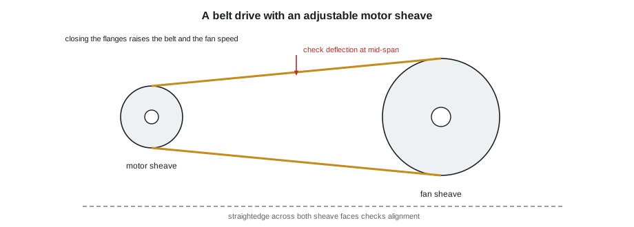
There are two ways to change the ratio. Many smaller fans have an adjustable-pitch motor sheave, also called a variable-pitch sheave, whose two flanges can be screwed closer together or further apart. Moving them closer makes the belt ride further out, increasing the effective diameter and the fan speed; moving them apart lowers it. The adjustment is made in half or full turns of the movable flange, and each turn changes the pitch diameter by a small, known amount listed by the sheave manufacturer. Larger fans, and fans after final balancing, usually have fixed-pitch sheaves; the speed is changed by replacing one sheave with another of a different diameter, selected from the manufacturer's catalog.
Adjustable sheaves are convenient during balancing but run belts at a less than ideal angle and wear faster. Many specifications require the TAB contractor to replace adjustable sheaves with fixed sheaves of the right size after balancing, and the TAB report records the final sheave and belt sizes so the owner can order replacements.
Checking the motor before speeding up a fan
Lesson 3 showed that fan power rises with the cube of speed. Before any speed increase, the technician estimates the new power and compares it with what the motor can deliver. The motor nameplate gives its rated power, full-load current, voltage, speed and service factor. The present load is estimated from measured current and voltage; for a three-phase motor, input power is about the square root of 3 times voltage times current times power factor, and the shaft power is that times the motor efficiency.
The power factor and efficiency at part load are not usually known precisely, so a simpler check is used as well: measured current compared with nameplate full-load current. Measured current near or above full-load current means the motor is already near its limit. A fan speed increase that would push the current past the nameplate value, or past the service factor current on a motor with a service factor above 1.0, needs a larger motor, and that is a design change for the engineer, not an adjustment for the balancer.
import math
# RTU-2 supply fan: estimate motor load now and after the speed increase needed to reach design
v, i_meas = 460, 2.6          # measured voltage and average current
fla = 3.6                  # nameplate full-load current
pf, eff = 0.8, 0.87        # assumed power factor and efficiency near this load
p_in = math.sqrt(3) * v * i_meas * pf / 1000
p_shaft = p_in * eff
print(f"current {i_meas} A = {100*i_meas/fla:.0f}% of full load; shaft power about {p_shaft:.2f} kW")
ratio = 1.16              # speed ratio needed (design / measured airflow)
p_new = p_shaft * ratio**3
i_new_est = i_meas * ratio**3 * 0.9   # current rises a little less than power at higher load
print(f"after speed-up: shaft power about {p_new:.2f} kW, current about {i_new_est:.1f} A ({100*i_new_est/fla:.0f}% of full load)")
print("within the nameplate" if i_new_est <= fla else "exceeds the nameplate: report, do not speed up")current 2.6 A = 72% of full load; shaft power about 1.44 kW after speed-up: shaft power about 2.25 kW, current about 3.7 A (101% of full load) exceeds the nameplate: report, do not speed up
RTU-2's motor is a 3 hp unit on a 460 V supply. At the first speed it drew 2.6 A against a full-load current of 3.6 A. The estimate after a 16 percent speed increase is about 3.7 A, slightly over the nameplate. Marisol does not accept a motor running over its nameplate. Before deciding, she and Kai looked for avoidable losses in the system, which is the right order: reduce the resistance the fan has to overcome before asking the motor for more.
Reducing losses before increasing speed
The static pressure profile taken during the traverse, lesson 5, shows where the system's pressure goes. On RTU-2 the filters and coil were close to their submittal values, but the return connection near the beam, flagged in Marisol's design review as a possible inlet problem, showed a larger loss than expected. The return duct made a tight turn into the side of the unit, and the turning vanes Sean's crew had fitted were set at the wrong angle, a mistake that is easy to make on a field-fabricated elbow. Resetting the vanes cut the return loss by about a third. The fan, now working against less resistance, delivered more air at the same speed, and the speed increase needed to reach design fell to about 12 percent.
Other common avoidable losses include balancing dampers left more closed than necessary, a closed or partly closed fire damper, a flexible connection twisted or stretched, construction debris in the duct, and in packaged units, a filter rack that bypasses air or forces it through a smaller area than intended. Each of these is cheaper to fix than a larger motor, and each one reduces the energy the building will use for the rest of its life.
Making the adjustment
With the motor check done, the unit is locked out under the site's lockout procedure and the belt guard is removed. On an adjustable sheave, the set screw on the movable flange is loosened, the flange is turned the calculated number of turns, and the set screw is retightened on the flat of the hub. The belt tension is then reset, because changing the pitch diameter changes the belt's position. On a fixed sheave, the old sheave is removed with its bushing and the new one fitted, aligned and secured.
# Sheave change for RTU-2: find the motor sheave pitch diameter for the target fan speed
motor_rpm = 1745
fan_sheave = 9.0         # fan sheave pitch diameter, in
motor_sheave = 5.42       # present motor sheave pitch diameter, in
n_fan = motor_rpm * motor_sheave / fan_sheave
print(f"present fan speed {n_fan:.0f} rpm")
target = n_fan * 1.12      # speed ratio needed after the return losses were reduced
d_needed = target * fan_sheave / motor_rpm
print(f"target {target:.0f} rpm needs a motor sheave of {d_needed:.2f} in")
per_turn = 0.19           # pitch change per full turn of the movable flange, in
print(f"on the adjustable sheave: about {(d_needed - motor_sheave)/per_turn:.1f} turns closed")present fan speed 1051 rpm target 1177 rpm needs a motor sheave of 6.07 in on the adjustable sheave: about 3.4 turns closed
The calculated number of turns is a starting point. After the adjustment the unit is restarted, and the fan speed, airflow, current and static pressure are read again. Usually a further small correction is needed. Once the speed is right, many specifications call for a fixed sheave of the equivalent diameter to be fitted, and the final speed and current confirmed.
Belt alignment and tension
Misaligned or loose belts wear quickly, slip, squeal and change the fan speed. After every sheave change the technician checks alignment with a straightedge or a laser alignment tool laid across the faces of both sheaves: the faces should be in one plane, with no angle or offset. Tension is checked by pushing the belt at the middle of its span with a tension gauge and measuring the deflection and force against the manufacturer's values, typically a deflection of about 1/64 of the span length at a specified force. New belts stretch during their first hours of running, so the tension is checked again after a day or two. Multiple-belt drives need matched sets, all replaced together.
Direct-drive fans and variable-frequency drives
Direct-drive fans, including plenum fans in modern air handlers and small exhaust fans, have no sheaves. Their speed is set by a variable-frequency drive, which changes the frequency of the power to the motor, or on small fans by an electronically commutated motor's speed setting or a multi-tap motor. On a constant-volume system with a VFD, the TAB technician has the drive's speed set to the frequency that gives design airflow, usually by the controls contractor or the drive's keypad, and records it. The drive's own display of speed and current is useful but is confirmed with a tachometer and clamp meter, because displays can be scaled or offset.
VFDs make balancing easier and save energy, because the fan can be slowed to exactly the speed needed instead of throttling with dampers. They also make it tempting to run fans faster than their motors and drives should, so the same motor checks apply. A drive set to run above 60 hertz to gain more airflow is running the motor above its base speed, where its torque capability falls and its bearings and the fan wheel may exceed their limits; this is done only with the manufacturer's and engineer's approval.
Final fan readings
With the fan at its final speed, the TAB technician records the full set of fan data for the report: airflow by traverse, fan speed, motor current on each phase and voltage, static pressure at the inlet and outlet and the profile through the unit, filter pressure drop, sheave sizes and positions or drive frequency, and belt sizes and tension. These figures are the baseline for every future service call; a mechanic who finds the current up or the airflow down years later can compare against them.
Worked problem
Final adjustment of RTU-2
After the return vanes are reset, RTU-2 delivers 3,120 cfm with the library proportioned at 86 percent of design. The fan runs at 1,050 rpm with a 5.42 in motor sheave and a 9.0 in fan sheave. What speed and sheave are needed?
Show solution
- Speed ratio for design: 3,500 ÷ 3,120 = 1.12.
- Target speed: 1,050 × 1.12 = 1,176 rpm.
- Motor sheave needed: 1,176 × 9.0 ÷ 1,745 = 6.07 in.
- That is (6.07 − 5.42) ÷ 0.19 ≈ 3.4 turns closed on the adjustable sheave; the motor current check after the change confirms it is within nameplate.
Answer: With the return loss reduced, a 12 percent speed increase is enough, and the motor stays within its nameplate. Lesson 12 completes the final readings.
Variable-frequency drives and balancing
Many fans now run on a variable-frequency drive, and the TAB technician sets the maximum airflow by adjusting the drive's frequency rather than changing sheaves. The same checks apply: total airflow by traverse, motor current against the nameplate, and the drive's displayed speed checked against a tachometer reading on the shaft. On a VAV system the drive is usually controlled by a static pressure loop, so the technician works with the controls contractor to set the loop at the lowest set point that still lets every terminal reach its maximum. A fixed sheave ratio is still worth checking on a belt-driven fan with a drive, because a badly chosen ratio can force the drive to run near its limits all the time.
Common mistakes
MistakeSpeeding up a fan without estimating the motor load.
InsteadApply the cube law and compare the estimated current with the nameplate first.
MistakeAsking for a bigger motor before checking system losses.
InsteadUse the pressure profile to find and fix avoidable losses.
MistakeAdjusting a sheave with the unit running or the guard off and live.
InsteadLock out the unit and replace the guard before restarting.
MistakeLeaving belts misaligned or at the wrong tension after a sheave change.
InsteadAlign with a straightedge or laser and set tension, then recheck after run-in.
MistakeRunning a VFD above base frequency to gain airflow.
InsteadDo it only with manufacturer and engineer approval.
Summary and key terms
- Fan speed on a belt drive is set by the ratio of sheave pitch diameters.
- Adjustable sheaves change pitch with flange turns; fixed sheaves are swapped.
- Check motor current and estimated power against the nameplate before speeding up.
- Reduce system losses found in the pressure profile before increasing speed.
- Align belts, set tension and recheck after run-in.
- Direct-drive fans are set with VFDs or EC motors; record final speeds, currents and pressures.
- Sheave
- A grooved pulley on a motor or fan shaft that carries V-belts.
- Pitch diameter
- The effective diameter at which a belt rides in a sheave.
- Adjustable-pitch sheave
- A sheave with a movable flange that changes its pitch diameter.
- Full-load current
- The current a motor draws at its rated power, from the nameplate.
- Service factor
- A nameplate multiplier for the load a motor can carry continuously above its rating.
- Variable-frequency drive
- A controller that changes motor speed by changing the supply frequency.
Practice problems
Work each problem on paper first, then reveal the answer to check.
A 1,750 rpm motor with a 4.5 in sheave drives a 9.0 in fan sheave. What is the fan speed?
Show answer
1,750 × 4.5 ÷ 9.0 = 875 rpm.
What motor sheave gives 950 rpm on the same fan?
Show answer
950 × 9.0 ÷ 1,750 = 4.89 in.
A 460 V motor draws 3.0 A. With power factor 0.82, what is the input power?
Show answer
1.732 × 460 × 3.0 × 0.82 ÷ 1,000 = 1.96 kW.
Why are belts rechecked after a day or two?
Show answer
New belts stretch during run-in and lose tension.
Lesson quiz · 5 questions
Score 60% or more to complete this lesson.
Create a free account to save your progress, take quizzes and earn a certificate.