
SMW-330 · Lesson 2 of 12 · 20 min
Air pressure and airflow principles
Every reading a TAB technician takes is either a pressure, a velocity or something calculated from them. Before Kai could use a pitot tube or trust a flow hood, Marisol made him work through what the numbers mean: why there are three kinds of pressure in a duct, how a pressure difference becomes a velocity, and why the same instrument reading means a different airflow on a cold morning on the Ashgrove roof than in a warm mechanical room. This lesson builds that foundation. RAC-330 introduced pressure and airflow for residential systems; here the same ideas are applied to the larger commercial ducts and fans that sheet metal workers balance.
Three pressures in a duct
Air moving in a duct carries two kinds of pressure. Static pressure is the pressure the air exerts in all directions, pushing outward on the duct walls whether the air is moving or not. In a supply duct downstream of a fan it is above atmospheric (positive); in a return or exhaust duct upstream of a fan it is below atmospheric (negative). Velocity pressure is the extra pressure that appears when moving air is brought to rest, as it is at the open end of a tube pointing into the flow. It is always positive, because it comes from the motion itself, and it depends only on the air's speed and density. Total pressure is the sum of the two.
Static and total pressure are measured relative to the atmosphere around the duct, so they are gauge pressures. Velocity pressure is not measured directly: it is the difference between total and static pressure, and that is exactly what a pitot tube connected to a manometer reads. The pitot tube has an opening facing into the airflow, which senses total pressure, and a ring of small holes around its side, which sense static pressure. Connecting the two to the two sides of a manometer gives velocity pressure.
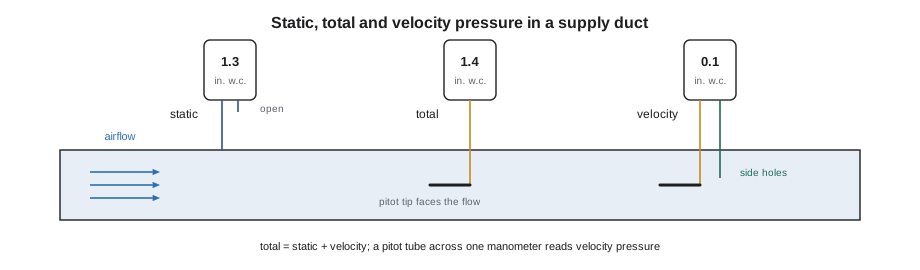
Pressures in air systems are small, so they are measured in inches of water column (in. w.c.), the height a column of water would be pushed up a manometer tube. A typical supply trunk might run at a static pressure of 0.8 to 2 in. w.c., and the velocity pressure in a main duct moving air at 1,500 fpm is about 0.14 in. w.c. Some instruments also read in pascals, where 1 in. w.c. is about 249 Pa.
From velocity pressure to velocity
Velocity pressure is the kinetic energy of the moving air per unit volume. That gives a direct relationship between the reading and the speed, which every TAB calculation uses.
Here V is in feet per minute (fpm), the velocity pressure is in inches of water column and the density in pounds per cubic foot. Because velocity goes with the square root of velocity pressure, a reading four times larger means only twice the speed. That is why small velocity pressures are hard to read accurately: at 200 fpm the velocity pressure is only about 0.0025 in. w.c., and an instrument error of a thousandth of an inch becomes a large percentage error in speed. TAB standards set a minimum velocity, and therefore a minimum velocity pressure, below which a pitot reading should not be used.
From velocity to airflow
Airflow is the volume of air passing a point per unit time. It is the average velocity across the duct times the duct's cross-sectional area. The key word is average. Air moves fastest near the center of a duct and slowest near the walls, and after an elbow or a branch the profile is lopsided. A single reading at the center overstates the flow, which is why lesson 5 is devoted to traverses that average many readings across the section.
For trunk T1 at Ashgrove, 36 × 18 in, the inside area is 4.5 ft². At the design 3,500 cfm the average velocity is 3,500 ÷ 4.5 = 778 fpm, which is a comfortable school velocity and gives a velocity pressure of about 0.038 in. w.c., high enough to read well with a good digital manometer.
Lined duct needs care with area: the airflow area is inside the liner, not the sheet metal. T1 is lined for its first few meters off the unit, which reduces its free area, and Marisol's rule is always to use inside dimensions measured at the test location, not the sizes on the drawing.
Air density and standard air
The velocity formula contains the air's density. Density falls as temperature rises and as barometric pressure falls, so it changes with the weather, the season and the elevation of the site. TAB calculations are usually done for standard air, a defined reference condition, and corrected when the actual air differs enough to matter.
Standard air is taken as dry air at 70°F and 29.92 in. Hg, with a density of 0.075 lb/ft³. Cleveland sits about 650 ft above sea level, where the standard barometric pressure is about 2 percent lower, and temperature matters as much: supply air at 55°F is about 3 percent denser than standard, and air in a heating duct at 105°F is about 6 percent lighter. A pitot reading in light, warm air means a higher actual velocity than the standard-air formula gives.
import math
# Velocity and airflow from a pitot velocity pressure, with a density correction
vp = 0.038            # average velocity pressure, in. w.c.
area = 4.5           # inside duct area, sq ft
t = 55.0              # air temperature, deg F
baro = 29.2           # barometric pressure, in. Hg
rho_std = 0.075
rho = 1.325 * baro / (t + 459.67)          # ideal-gas density from temperature and pressure
v_std = 4005 * math.sqrt(vp)          # standard-air velocity
v_act = v_std * math.sqrt(rho_std / rho)  # actual velocity at this density
print(f"density {rho:.3f} lb/ft3 (standard {rho_std})")
print(f"velocity: standard-air formula {v_std:.0f} fpm, corrected {v_act:.0f} fpm")
print(f"airflow: {v_act * area * 1:.0f} cfm actual")density 0.075 lb/ft3 (standard 0.075) velocity: standard-air formula 781 fpm, corrected 780 fpm airflow: 3509 cfm actual
The correction here is small, because the air is cool and the site is low. On a heating test, or at a site at high elevation, it is not small, and an uncorrected reading can be off by 5 to 10 percent, which is the whole tolerance. The TAB report states whether flows are given as actual or standard and, if corrected, the conditions used. Many digital manometers do the correction automatically if the technician enters temperature and barometric pressure, which is why Kai's checklist includes reading both at the start of each day.
Pressure and the system
Static pressure drops as air flows through a duct, because friction and turbulence turn some of its energy into heat. A fan adds pressure; every duct, fitting, coil, filter, damper and outlet takes some away. Plotting static pressure along a system, from the return grille through the unit to the farthest supply outlet, gives a pressure profile that tells a technician a great deal. A large drop across a filter means it is loaded; a large drop across a coil may mean it is wet or dirty; a sudden loss at one fitting may mean a crushed duct or a closed damper. Lesson 4 describes how the profile is taken.
Velocity pressure and static pressure can trade with each other. Where a duct gets larger, the air slows, velocity pressure falls and some of it is recovered as static pressure; where a duct gets smaller, the reverse happens. That is why a static pressure reading taken just downstream of a transition can be misleading, and why test holes are placed in straight duct where the flow has settled.
Two terms from fan selection come up constantly. External static pressure is the static pressure difference between the unit's supply and return connections, the pressure the fan has to supply to the ductwork outside the unit. Total static pressure includes the internal losses of the unit as well, such as filters, coils and the casing. Both appear on equipment schedules and fan curves, and confusing them is one of the most common errors in a TAB report.
Worked problem
Velocity pressure at Eastgate
At Eastgate, a 16 in round exhaust duct serving an isolation suite reads an average velocity pressure of 0.058 in. w.c. at 70°F. What are the velocity and the airflow?
Show solution
- Air at 70°F is close to standard, so use V = 4005 √0.058 = 4005 × 0.241 = 965 fpm.
- Area of a 16 in duct: π × (16/12)² ÷ 4 = 1.40 ft².
- Airflow: 965 × 1.40 = 1,350 cfm.
Answer: The exhaust duct is moving about 1,350 cfm, which the TAB group compares with the scheduled exhaust for the suite.
Reading pressure in the field without fooling yourself
Most pressure mistakes on a TAB job come from the setup, not the arithmetic. Before Marisol lets a new technician take a reading, she has them zero the manometer with both ports open to the same air, check that the tubing has no kinks or water in it, and confirm which port is high and which is low. A reversed hose on a static pressure reading gives a number with the wrong sign, and a technician in a hurry may simply write down the magnitude. On a return or exhaust duct the static pressure really is negative, so the sign is information, and Marisol wants it recorded as read.
Static taps need care as well. A hole drilled with a ragged edge, or a tap that projects into the airstream, reads high or low depending on which way the burr points. A clean, square hole flush with the inside of the duct wall reads the true static pressure. Where the duct is lined, the probe has to pass through the liner without catching on it, and the hole is closed afterwards with a proper plug rather than tape, so the reading point can be used again during commissioning and the lining does not fray into the airstream.
Fluctuating readings are common near fans and fittings. A digital manometer can average over several seconds, and most TAB technicians set it to do so rather than trying to read a dancing number by eye. If the reading still swings widely, the location is the problem. Moving the probe a few duct diameters further from the elbow or the fan usually settles it, and the steadier reading is the more trustworthy one. Kai learned this on his first day at Ashgrove, when a reading right after the RTU-2 discharge transition swung by more than 0.15 in. w.c. and the same duct ten feet downstream held steady.
Why the velocity pressure is so small
Students are often surprised by how small velocity pressure is compared with static pressure. In the RTU-2 example, the static pressure is 1.3 in. w.c. and the velocity pressure only 0.1 in. w.c.. That is normal in supply ducts, where the fan's job is mostly to overcome friction and fitting losses. It also explains why velocity pressure readings need a sensitive instrument and a steady hand: a small error in a small number is a large percentage error in the airflow, even though the square root halves it.
The square root works in the technician's favor in one way. Because velocity varies with the square root of velocity pressure, a 10 percent error in a pressure reading becomes roughly a 5 percent error in velocity. It works against the technician in another: at low velocities, a fixed instrument error of a pascal or two becomes a large fraction of the reading. That is why low-velocity ducts and outlets are measured with other instruments, which Lesson 4 describes, and why a traverse in a slow duct is planned with extra care over where the plane sits.
Units on the job
TAB work mixes units more than most trades. Equipment from one manufacturer may list airflow in cubic feet per minute while a submittal from another lists it in another unit, and older drawings in the same building may use different units again. Marisol's rule is that every number written on a field sheet carries its unit, and every conversion is done once, on the sheet, where the reviewer can see it. A missing unit has cost her crews more time than any instrument failure, because a number without a unit cannot be checked later.
Common mistakes
MistakeReading a single center-line velocity and multiplying by the area.
InsteadAverage many readings across the section with a traverse.
MistakeUsing the drawing size of a lined duct as its airflow area.
InsteadMeasure inside the liner at the test location.
MistakeIgnoring air temperature on a heating test.
InsteadCorrect for density, or report flows at the conditions measured.
MistakeConfusing external static pressure with total static pressure.
InsteadExternal static pressure excludes the unit's internal losses.
MistakeTaking a static reading right after a transition.
InsteadMeasure in straight duct where the flow has settled.
Summary and key terms
- Total pressure is static plus velocity pressure; a pitot tube reads the difference as velocity pressure.
- Velocity goes with the square root of velocity pressure; small readings are hard to read accurately.
- Airflow is average velocity times inside area.
- Density changes with temperature and elevation; standard air is the usual reference.
- Static pressure profiles locate loaded filters, dirty coils and blockages.
- External static pressure is what the fan supplies to the ductwork outside the unit.
- Static pressure
- Pressure exerted in all directions by the air, measured at the duct wall.
- Velocity pressure
- The pressure due to the air's motion; total minus static pressure.
- Total pressure
- The sum of static and velocity pressure.
- Pitot tube
- A probe with a facing opening and side holes that reads total and static pressure.
- Standard air
- A reference air condition with a defined density used in TAB calculations.
- External static pressure
- The static pressure difference across the unit's duct connections.
Practice problems
Work each problem on paper first, then reveal the answer to check.
A pitot reads 0.10 in. w.c. velocity pressure in standard air. What is the velocity?
Show answer
4005 × √0.10 = 1,267 fpm.
A 24 × 18 in duct has an average velocity of 1,000 fpm. What is the airflow?
Show answer
3.0 ft² × 1,000 = 3,000 cfm.
Static pressure is 1.30 in. w.c. and total pressure 1.40 in. w.c. What is the velocity pressure?
Show answer
1.40 − 1.30 = 0.10 in. w.c.
Why does warm air give a higher actual velocity for the same velocity pressure?
Show answer
It is less dense, and velocity goes with the square root of pressure divided by density.
Lesson quiz · 5 questions
Score 60% or more to complete this lesson.
Create a free account to save your progress, take quizzes and earn a certificate.