
SMW-120 · Lesson 5 of 12 · 13 min
Round pipe and pipe cut at an angle
Round pipe is the shape that makes parallel line development worth learning. A rectangular prism has only four element lines, its corners. A pipe has infinitely many, and the pattern maker picks a set of them, spaced equally around the circumference, to stand for the whole surface. Once a pipe cut at an angle can be developed, every round elbow, tee and offset in this course is the same pattern repeated, flipped or combined. This lesson develops the plain pipe and the pipe cut by a sloping plane, step by step, and explains how many divisions to use, where to put the seam and how to draw a smooth curve through the points.
The plain pipe
A round pipe cut square at both ends develops into a rectangle. Its height is the length of the pipe, and its width, the stretchout, is the circumference at the mean diameter. SMW-110 introduced the reason. When a flat sheet is rolled into a cylinder, the outside surface stretches and the inside compresses, and the layer that keeps its length is near the middle of the thickness. So the stretchout is pi times the mean diameter, which is the inside diameter plus one thickness, or the outside diameter minus one thickness.
For the 10 in Ashgrove branch ducts in 24-gauge galvanized steel, 0.0276 in thick, specified to their outside diameter, the mean diameter is 9.972 in and the stretchout 31.33 in. Using the outside diameter instead would make the pattern about 3/32 in too long, enough for the seam to close loose; using the inside diameter would make it about 3/32 in too short, and the duct would not fit over its collar.
To the stretchout are added the allowances for the longitudinal seam, and to the ends the allowances for whatever joint connects the pipe to its neighbors, such as a crimp, a bead or a slip collar. Lesson 11 covers them. For this lesson, patterns are drawn net.
Dividing the pipe
To develop a cut pipe, the circumference is divided into equal spaces, and an element line is drawn at each division. In the half plan, the half circle is divided into equal parts; Lesson 1's construction with the radius gives six parts on a full circle and 12 when bisected. Each division of the half plan stands for two element lines, one in front and one behind, so a half plan of six spaces gives 12 element lines on the full pipe.
How many divisions to use is a judgment between accuracy and work. More element lines give more points on the pattern curve and a truer shape, but every point is one more chance for an error and one more height to transfer. Aggie's shop rule was 12 spaces for pipe up to about 12 in, 16 up to about 24 in, and 24 or more above that. The rule follows from the spacing between element lines: on a 10 in pipe, 12 spaces are about 2 5/8 in apart, close enough that a smooth curve through the points is accurate. On a 36 in pipe, 12 spaces would be over 9 in apart, and the curve between points would be guesswork.
The divisions on the stretchout must equal the divisions of the circumference, not the chords of the half plan. Lesson 1 explained why: a chord is shorter than its arc, so dividers stepped around the half plan and then stepped along the stretchout would give a pattern too short by about 1 percent for 12 spaces. The correct method is to calculate the stretchout, lay it out as one straight line, and divide that line into 12 equal parts by measurement or by Lesson 1's construction.
A pipe cut at an angle
Now cut the pipe with a plane that is not square to its axis. In the elevation, the cut appears as a straight sloping line, called the miter line. The element lines are straight and parallel to the pipe's axis, so each one ends where it meets the miter line, and each has a different length. The longest is on one side of the pipe, called the heel or long side; the shortest is on the other, the throat or short side; the rest vary smoothly between.
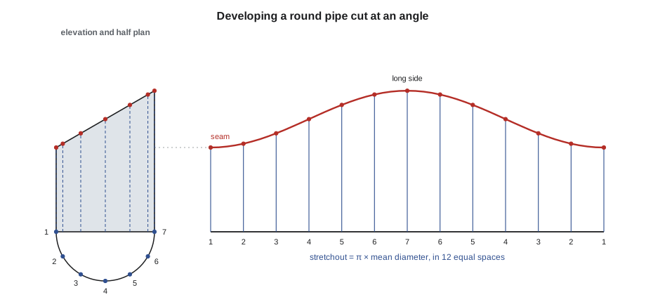
Following Lesson 3's sequence, Kai developed the 30-degree branch from Lesson 2. He drew the elevation full size with a base line square to the pipe, and the half plan as a half circle on the base, divided into six equal parts and numbered 1 at the short side to 7 at the long side. He projected each point up into the elevation as an element line and marked where it met the miter line. He drew the stretchout as an extension of the base line, calculated its length, divided it into 12 equal spaces and numbered them 1, 2, 3, 4, 5, 6, 7, 6, 5, 4, 3, 2, 1, so that the short side was at both ends where the seam would be and the long side in the middle. Then he projected each height across from the elevation to the element lines with the same number, and joined the points.
The resulting cut edge is a smooth wave, low at both ends and high in the middle. It is not a circle arc and not a series of straight lines. For a cut by a plane, it is exactly a sine curve, which is a useful fact for checking but not something a pattern maker usually draws from the formula.
The arithmetic behind the curve
For a pipe of mean radius r cut by a plane tilted at angle α from square, the cut rises across the pipe by the mean diameter times the tangent of α. An element line at angle φ around the pipe, measured from the short side, is longer than the shortest element by r times the tangent of α times one minus the cosine of φ. That formula gives every height on the pattern without drawing the elevation at all, and it is how CNC pattern software and plasma tables produce cut pipe patterns.
The script uses it to print a table of ordinates, the heights of every element line, for a pipe cut at any angle and divided into any number of spaces. A table like this is what an experienced pattern maker writes on the back of a drawing before laying out, and it is a strong check on a drawn layout.
# Ordinates for a round pipe cut at an angle (parallel line pattern)
import math
d_out, t = 10, 0.0276      # in                 # outside diameter and thickness
h_min = 12.25           # in                  # shortest element (the seam)
tilt = 30                   # degrees from a square cut
spaces = 12
dm = d_out - t                  # mean diameter
r = dm / 2
stretch = math.pi * dm
print(f"stretchout {stretch:.3f} in, {spaces} spaces of {stretch / spaces:.3f} in")
for k in range(spaces + 1):
    phi = 2 * math.pi * k / spaces              # 0 at the short side
    h = h_min + r * math.tan(math.radians(tilt)) * (1 - math.cos(phi))
print(f"line {k:>2} at {k * stretch / spaces:>6.3f} in: height {h:.3f} in")stretchout 31.329 in, 12 spaces of 2.611 in line 0 at 0.000 in: height 12.250 in line 1 at 2.611 in: height 12.636 in line 2 at 5.222 in: height 13.689 in line 3 at 7.832 in: height 15.129 in line 4 at 10.443 in: height 16.568 in line 5 at 13.054 in: height 17.622 in line 6 at 15.665 in: height 18.008 in line 7 at 18.275 in: height 17.622 in line 8 at 20.886 in: height 16.568 in line 9 at 23.497 in: height 15.129 in line 10 at 26.108 in: height 13.689 in line 11 at 28.718 in: height 12.636 in line 12 at 31.329 in: height 12.250 in
Kai's drawn heights all agreed with the table to within 1/32 in except one, line 4, where he had projected from the wrong point on the miter line. The table caught it before he cut.
Drawing a smooth curve
The points on a pipe pattern are joined with a smooth, fair curve, one that changes direction gradually with no flat spots or kinks. On paper, pattern makers use a French curve or a flexible curve, a bendable strip that holds its shape. On sheet metal, the usual tool is a thin flexible steel or plastic batten, held against small weights or nails at the points and traced with a scriber or marker. Whatever the tool, the curve should pass through every point, and if one point will not lie on a smooth curve through its neighbors, that point is probably wrong and should be rechecked rather than forced.
The high and low points of the curve need particular care. At the short side and the long side, the curve is level, running parallel to the stretchout, because the element lines on either side of those points are the same length. A curve that comes to a point at the long side, or that is not level at the seam ends, will make a fitting with a visible ridge at the joint.
Cutting the curve follows SMW-110. The curve is cut with straight or offset aviation snips, or on the shop's plasma table if the pattern was produced by software, and the cut is kept on the waste side of the line so that the line is still visible on the finished edge for checking.
Where the seam goes on a cut pipe
The seam goes on the short side of the cut, as it did for the prism in Lesson 3. There are three reasons. The short side is the shortest element, so the seam uses the least material and is the easiest to close. The seam ends cleanly at the cut, where the curve is level. And when two cut pipes join to make an elbow, as they will in Lesson 6, the short side of one becomes the joint with the long side of the other, which keeps seams from lining up across the joint. Some specifications ask for the seam at the side or at the top for appearance; the method is the same, and the numbering simply starts at the seam wherever it is.
Patterns from templates
A shop that makes the same fitting often keeps a hard pattern, a template cut from heavier sheet, for each size and angle. The template is laid on the blank and traced, which is faster and more consistent than developing the pattern every time. Templates have one weakness: they are only correct for the thickness they were developed for, because the stretchout depends on the mean diameter. A template made for 24-gauge duct is slightly long for heavier material and slightly short for lighter, and Walt's templates were each marked with the diameter, the angle and the gauge.
Pipe cut at an angle for flashings and roof jacks
The pipe cut at an angle is not only a duct fitting. A round roof jack, the sleeve that carries a vent pipe through a sloped roof, is a pipe cut at the roof's pitch, and its flange is cut to the same curve. A round downspout entering a sloped gutter outlet is the same shape. At St. Brendan's, the old cast iron vent pipes were being sleeved in copper where they passed through the roof, and each sleeve was developed exactly as in this lesson, with the cut angle taken from the roof pitch. For a roof of 8 in 12, the angle is the arctangent of 8 over 12, about 33.7 degrees, and the sleeve's pattern rises across the pipe by its mean diameter times two-thirds.
On architectural work the cut edge is visible, so the curve has to be fair and the cut clean. Aggie had Kai cut copper sleeves with straight-cut snips held so the blade followed the curve gradually, never taking a bite at an angle to the line, and then dress the edge with a fine file. On a duct fitting a few small snip marks are acceptable inside a sealed joint; on a church roof they are not.
Rolling the cut pipe
A cut pipe pattern is rolled the same way as a plain pipe, but with care at the cut end. Feeding the blank into the slip roll with the curved edge first can catch the high part of the curve and buckle it, so the blank is fed with the square base edge leading and the seam allowances pre-formed. The cut edge then comes off the rolls last and follows the curve of the pipe without stress.
Common mistakes
MistakeDeveloping the stretchout from the outside or inside diameter.
InsteadUse the mean diameter: outside minus one thickness, or inside plus one.
MistakeStepping the chords of the half plan along the stretchout.
InsteadCalculate the stretchout and divide the straight line into equal spaces.
MistakeUsing 12 spaces on a large pipe.
InsteadUse 16 or 24 spaces as the diameter grows, so the points stay close together.
MistakeForcing the curve through a point that will not lie fair.
InsteadRecheck that point; it is probably wrong.
MistakeUsing a template made for a different gauge.
InsteadMark templates with diameter, angle and gauge, and use them only for that material.
Summary and key terms
- A plain pipe develops into a rectangle whose width is pi times the mean diameter.
- Divide the half plan equally; each division stands for two element lines.
- Use 12 spaces for small pipe and more for larger pipe.
- A pipe cut by a plane develops a smooth wave-shaped edge, low at the seam and high in the middle.
- Each height is the shortest height plus r tan α (1 − cos φ).
- Draw a fair curve with a batten, put the seam on the short side, and mark templates with their gauge.
- Mean diameter
- The diameter at the middle of the metal thickness.
- Mitre line
- The line of a cut or joint as it appears in the elevation.
- Heel
- The long side of a cut pipe or elbow.
- Throat
- The short side of a cut pipe or elbow.
- Ordinate
- The height of an element line on a pattern, measured from the base line.
- Batten
- A thin flexible strip used to draw smooth curves through points.
- Hard pattern
- A durable template kept for a fitting that is made often.
Lesson quiz · 5 questions
Score 60% or more to complete this lesson.
Create a free account to save your progress, take quizzes and earn a certificate.