
SMW-120 · Lesson 4 of 12 · 15 min
Square and rectangular prisms
Square and rectangular prisms are the simplest shapes in parallel line work and among the most common in the shop. A rectangular duct section is a prism. So is the casing that boxes a vent pipe through a roof, the curb under a rooftop unit, a downspout, a parapet coping and a chimney cricket's straight sides. When one of those is cut square, its pattern is a rectangle and needs no development at all. When it is cut on a slope or miterd to meet another piece, it needs the parallel line method, and because its faces are flat, the method is at its easiest. This lesson develops cut and miterd prisms and introduces the corner-seam layouts that make them practical to build.
A rectangular prism cut square
A rectangular prism cut square at both ends develops into a rectangle whose length is the perimeter and whose height is the length of the prism. On paper that is trivial. In the shop, the decisions are where to put the corners and seams, which matters more than the arithmetic. A small rectangular duct can be made from one sheet with one seam, folded on three corners and closed at the fourth. Larger ducts are made in two L-shaped pieces with two corner seams, or in four flat panels with four, so that each piece fits the sheet and the brake.
For the Ashgrove supply ducts, 24 × 16 in, Walt's shop standard was two L-shaped halves, each 24 + 16 = 40 in of girth plus seam allowances, with Pittsburgh locks at two diagonally opposite corners. One-piece wraps were used only for small ducts, up to about 12 × 8 in, where the whole girth fitted on a single blank and the brake could make all three bends.
Whatever the split, the stretchout is laid out along the bottom of the blank with the bend lines marked at each corner, so the folds land exactly on the corners of the finished prism. That is the parallel line method in its simplest form: the element lines are the corners, and the spaces between them are the sides.
A rectangular prism cut on a slope
Now cut the prism by a plane that slopes in one direction, the way a vent casing is cut where it passes through a sloped roof. Two of the four faces become trapezoids, and two stay rectangles but with different heights. The method is exactly Lesson 3's. In the elevation, draw the prism and the sloped cut. In the plan, number the corners 1 to 4. Project the corners into the elevation to find their heights at the cut. On the stretchout, lay off the four sides in order, erect element lines at the corners, and carry the heights across. Join the points with straight lines.
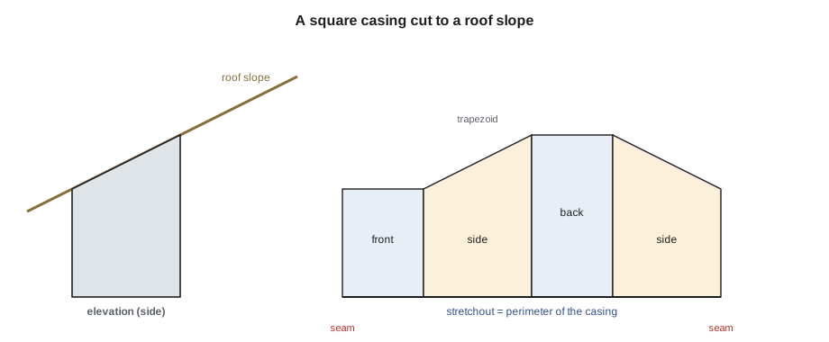
The rise of the cut across the prism is the width of the prism in the direction of the slope times the slope, expressed as a rise per unit of run. A roof of 6 in 12, a common pitch, rises 0.5 units per unit of run, so a casing 12 in deep in the direction of the slope has a front face 6 in shorter than its back face. A pattern maker working from a roof pitch converts it to an angle or a ratio first, because the drawing may give it either way.
The script develops a rectangular casing cut by a sloped roof. It prints the height of each corner on the pattern, along with the position of each corner along the stretchout, in a table ready to lay out.
# Pattern for a rectangular casing cut by a sloped roof (cut slopes along the depth)
width, depth = 10, 12          # in             # width across the slope, depth along the slope
h_front = 16              # in                  # height at the low (front) face
rise, run = 6, 12             # roof pitch
slope = rise / run
h_back = h_front + depth * slope
corners = [("1 front-left", 0, h_front), ("2 front-right", width, h_front),
           ("3 back-right", width + depth, h_back), ("4 back-left", 2 * width + depth, h_back),
           ("1 front-left (seam)", 2 * (width + depth), h_front)]
print(f"stretchout {2 * (width + depth)} in, back face {h_back - h_front:.2f} in taller than front")
for name, x, h in corners:
print(f"{name:<22} at {x:>3} in height {h:.2f} in")stretchout 44 in, back face 6.00 in taller than front 1 front-left at 0 in height 16.00 in 2 front-right at 10 in height 16.00 in 3 back-right at 22 in height 22.00 in 4 back-left at 32 in height 22.00 in 1 front-left (seam) at 44 in height 16.00 in
Note that the seam was put on the front-left corner, at the low face, which keeps the seam short and on a corner where it can be formed as a corner lock. The two side faces of the pattern are the trapezoids; their sloping top edges are the true length of the cut along the sides, which is longer than the depth because it follows the slope.
A prism cut in two directions
A casing on a hip or valley, or a curb on a roof that slopes two ways, is cut by a plane that slopes in both directions. Then all four corners have different heights. The method does not change: each corner's height is found in the elevation and the profile, using both views, and carried to its element line. This is where the labeling habit of Lesson 2 pays off. A pattern maker who labels the corners the same way in the plan, elevation and profile can read the height of any corner from whichever view shows it, and has nothing to guess.
For a plane cut, the heights also obey a simple rule that makes a good check: the heights of diagonally opposite corners add up to the same total. If corners 1 and 3 add to 40 in, corners 2 and 4 must too. A pattern that fails that test has a height wrong.
Mitred prisms: copings and gutters
Where two prisms meet at a corner, each is cut on the line that bisects the angle between them, the miter. A parapet coping turning a 90-degree corner is two prisms miterd at 45 degrees. A gutter turning a corner is the same, although its cross-section is not a closed prism but an open profile; the method works identically, because the profile's bends are its element lines. For the St. Brendan's restoration, the church's parapet had a copper coping turning four outside corners and two inside corners, and every one needed a miterd pattern.
To develop a miterd profile, draw the profile, its cross-section, as an end view, and number each bend and each end of the profile. Draw the plan of the corner with the miter line on the bisector of the angle, using Lesson 1's construction. Project each numbered point of the profile into the plan as an element line running along the coping, and mark where each meets the miter line. Then lay out the stretchout of the profile, which is the developed length of the profile through all its bends, with the bend lines numbered in order. Erect element lines at each bend and carry across from the plan the distance from a base line to the miter on each element line.
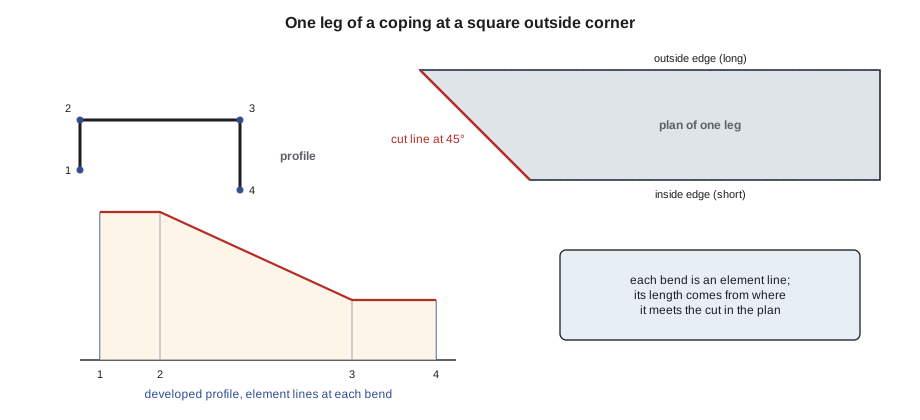
For a 90-degree corner, each element line's length to the miter changes by exactly its distance across the profile in plan, because the tangent of 45 degrees is one. For other corner angles, the change is the distance across times the tangent of half the angle by which the coping turns. Copings on buildings that are not square, and St. Brendan's had two corners of about 100 and 80 degrees, need that calculation or a full-size plan drawing of the actual corner.
Worked problem
A miterd coping for a 100-degree corner
One outside corner of the St. Brendan's parapet turns through 80 degrees, so the inside angle between the walls is 100 degrees. The coping is 12 1/2 in wide across its top in plan. How much longer is the outside edge of each leg than the inside edge at the miter?
Show solution
- \[\text{miter angle} = \tfrac{80^\circ}{2} = 40^\circ \text{ from square}\]
- \[\Delta L = 12.5 \times \tan 40^\circ = 12.5 \times 0.839 = 10.49\ \text{in}\]
Answer: About 10 1/2 in on each leg, so the miter runs at 40 degrees across the coping.
On a coping, the outside corner and the inside corner miter in opposite directions: at an outside corner the outer edge is the long one, and at an inside corner it is the short one. Kai cut his first inside-corner copper miter backward, which Aggie had expected, because nearly every apprentice does. That is why the first one is cut in galvanized scrap.
Corner seams and laps
A prism's corners are where the seams naturally go, and laying out the pattern so that the seam allowances fall at the corners is part of developing it. On duct, the corner seam is usually a Pittsburgh lock: a pocket formed on one edge and a single flange on the other, which is inserted and hammered over. On copings and flashings, miterd corners are usually lapped and soldered for copper or riveted and sealed for other metals, with a lap of 1 in or more. The allowance for each seam is added to the net pattern along the corner element line, and for a Pittsburgh lock it is different on the pocket and flange edges, so the two halves of an L-shaped duct are not identical. Lesson 11 gives the shop's allowances; SMW-130 explains the seams.
Material and bending order
Cut prisms are bent on the box and pan brake or the cornice brake, with the bending order planned so that the last bend is possible. For a one-piece wrap with a sloped top, the sloped edge is cut first, while the blank is flat, and the bends are made afterward, because cutting a sloped edge on a bent part is awkward and inaccurate. Where the cut edge needs a flange to turn out onto a roof deck, that flange is marked on the pattern and bent before the corners, and the corners of the flange are notched to clear each other. Kai's casing for a test piece had a 2 in deck flange, notched at 45 degrees at each corner, which he got right on his second attempt.
Polygonal prisms
Hexagonal and octagonal prisms appear in architectural sheet metal: finial bases, cupola sides, decorative column covers and lantern housings. They are developed exactly like the hexagon of Lesson 3: the stretchout is the number of sides times the side length, the element lines are the corners, and the heights come from the elevation. When a polygonal prism sits on a pitched roof, its corners meet the roof at heights that depend on each corner's position along the slope, and the same rule of diagonally opposite corners applies to every pair of corners directly across the polygon.
Octagonal work is where small angle errors grow. Each corner of a regular octagon is 135 degrees inside, so each corner bend on the brake is 45 degrees from flat. A bend of 44 degrees instead of 45 at each of the eight corners leaves a gap of eight degrees when the pattern is closed, which is very visible on a copper finial. Aggie had Kai make a 45-degree bending gauge from scrap and check every corner against it.
Laying prisms out for the brake
Before a cut prism pattern goes to the shear, the bend lines are marked on the face that will be inside, so the brake operator can line them up with the nose of the clamping bar. On galvanized and painted work they are marked with a fine marker; on stainless and copper, with a soft wax pencil that wipes off. The sloped top edge is cut first, then the corners are bent in an order that leaves the last bend accessible: for a one-piece wrap, the two middle corners first, then the outside ones, so that the seam corner is formed last with the most room.
The finished part is checked by setting it on a flat surface and laying a straightedge across the cut edge in several directions. For a plane cut, the straightedge touches the edge everywhere. A gap at one corner shows that its height, or its bend, is wrong.
Common mistakes
MistakeMitring an inside corner the same way as an outside corner.
InsteadOutside corners have the long edge outside; inside corners have it inside. Check on a sketch.
MistakeAssuming every building corner is 90 degrees.
InsteadMeasure the real angle and use the tangent of half the turn, or draw it full size.
MistakeCutting the sloped edge after bending.
InsteadCut sloped edges while the blank is flat, then bend.
MistakeMaking both halves of an L-shaped duct identical.
InsteadPocket and flange edges take different allowances; mark which half is which.
MistakeForgetting that diagonally opposite corner heights must add up equally.
InsteadUse that rule to check every plane-cut prism.
Summary and key terms
- A square-cut prism develops into a rectangle; the decision is where the corners and seams go.
- A prism cut on a slope has corners of different heights, found in the elevation and carried to the pattern.
- For a plane cut, diagonally opposite corner heights add up to the same total.
- Mitred copings and gutters use the profile's bends as element lines and the miter in plan for their lengths.
- Outside and inside miters run in opposite directions.
- Allowances go on the corner element lines; cut sloped edges flat, then bend.
- Mitre
- A joint between two pieces cut on the line bisecting the angle between them.
- Coping
- A sheet metal cap over the top of a wall or parapet.
- Pitch
- The slope of a roof, given as rise over run or as an angle.
- Profile
- The cross-section of a formed part such as a coping or gutter.
- Corner lock
- A seam formed along the corner of a prism, such as a Pittsburgh lock.
Lesson quiz · 5 questions
Score 60% or more to complete this lesson.
Create a free account to save your progress, take quizzes and earn a certificate.