
SMW-120 · Lesson 2 of 12 · 14 min
Orthographic views for layout
A pattern maker does not usually work from the object itself. The fitting does not exist yet; what exists is a drawing, and the pattern is taken from views of that drawing redrawn full size. The views are orthographic projections: flat pictures of the object as seen looking straight at it from the top, the front and the side. Reading those views, and drawing the ones that are missing, is the second foundation of pattern development, after the geometry of Lesson 1. This lesson covers how orthographic views work, what can and cannot be measured in them, and how a pattern maker uses them to find the true lengths and true shapes a pattern needs.
Lin Zhao, Keelson's detailer, drew most of the shop drawings that came out to the layout bench. On Kai's second day of the course she brought him a print of a fitting for the Ashgrove retrofit and asked him which lines on it were full length. He guessed all of them. She smiled and spent the next hour showing him why not.
How orthographic projection works
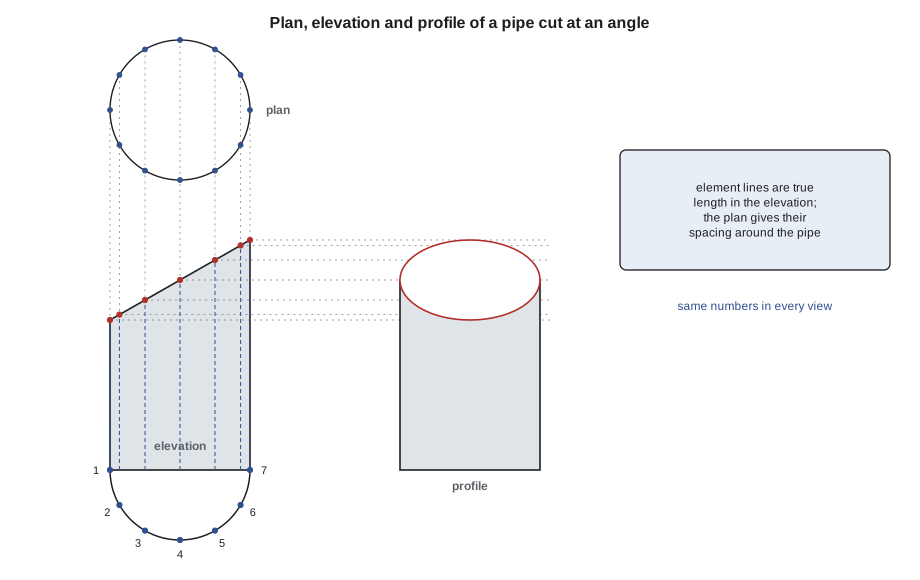
Imagine the object inside a glass box. Looking straight through each face of the box, square to it, and tracing what is seen onto the glass gives one view. The front face gives the front view or elevation; the top gives the top view or plan; the right side gives the right-side view or profile. Unfold the box flat and the views lie in a standard arrangement: the plan directly above the elevation, and the profile beside the elevation. Because the views are lined up, every point of the object appears in each view on a projection line. A point's left-right position is the same in the plan and the elevation, and its height is the same in the elevation and the profile.
US practice uses third-angle projection, with the plan above the elevation and the right-side view to the right of the elevation, and the projection symbol in the title block confirms it. Some drawings from European equipment makers come in first-angle projection, with the views swapped, so Lin always checked the projection symbol in the title block before anyone started layout.
For pattern work the most useful habit is to label points the same way in every view. If the top corner of a duct is A in the plan, it is A in the elevation and A in the profile. With consistent labels, projection lines can be drawn from point to point between views, and anything known in one view can be carried to the others.
True length and foreshortening
A line appears at its true length in a view only if it is parallel to the plane of that view. A vertical edge of a box is parallel to the front and side views, so it shows true length in both, but in the plan it points straight at the viewer and appears as a single point. A line that slopes in the elevation, such as the edge of a sloped roof or the cut edge of a pipe, appears shorter than its true length in the plan, because the plan sees it at an angle. This shortening is called foreshortening, and it is the reason a pattern cannot simply be traced from a view.
The rule for spotting a true length is simple. If a line appears parallel to the folding line between two views in one of them, it appears at true length in the other. A line that is horizontal in the elevation is parallel to the plan, so the plan shows it true length. A line that appears as a point in one view is perpendicular to that view and true length in any adjacent view. Lines that are inclined in every view are oblique lines, and their true lengths have to be found by construction, which is the core of triangulation in SMW-210.
Parallel line development is easier because it is used on objects whose element lines are all parallel and can be shown at true length in one view. For a straight pipe, the lines running along its length are parallel to its axis, and in the elevation they all show true length. That is why parallel line patterns are developed from the elevation: it holds the true lengths, and the plan holds the true spacing around the circumference.
True shape and auxiliary views
A flat face of an object shows its true shape only in a view parallel to it. The face of a pipe cut at 45 degrees is an ellipse, but in the plan it looks like a circle and in the elevation it looks like a straight line. Neither view shows its true shape. When a pattern maker needs the true shape of an inclined face, such as a cover plate for the cut end of a duct or the shape of a hole in a sloped roof, an auxiliary view is drawn, projected square to the inclined face rather than to the usual views.
To draw an auxiliary view, draw a reference line parallel to the edge view of the inclined face, which in the elevation is the sloped line. From each labeled point on that sloped line, project lines square to it. Measure the distance of each point from the center line in the plan and transfer it, with dividers, along the projection lines from a new center line drawn parallel to the reference line. Joining the points gives the true shape of the face. For a round pipe cut at an angle the true shape is an ellipse whose short axis is the pipe diameter and whose long axis is the diameter divided by the cosine of the cut angle.
The calculation behind it is a useful check. The long axis of the cut face equals the diameter divided by the cosine of the angle between the cut and a plane square to the pipe. A cut tilted 45 degrees has a long axis about 1.414 times the diameter; a cut tilted 30 degrees, about 1.155 times. The short axis stays equal to the diameter.
# True shape of a round pipe cut by an inclined plane: an ellipse
import math
diameter = 10    # in
for tilt in (15, 22.5, 30, 45, 60):         # degrees from a square cut
    long_axis = diameter / math.cos(math.radians(tilt))
print(f"cut tilted {tilt:>4} deg: long axis {long_axis:.3f} in, short axis {diameter} in")cut tilted 15 deg: long axis 10.353 in, short axis 10 in cut tilted 22.5 deg: long axis 10.824 in, short axis 10 in cut tilted 30 deg: long axis 11.547 in, short axis 10 in cut tilted 45 deg: long axis 14.142 in, short axis 10 in cut tilted 60 deg: long axis 20.000 in, short axis 10 in
Reading shop drawings for layout
Shop drawings for ductwork are rarely full orthographic sets. Duct shop drawings are usually a plan of the duct runs, with each fitting tagged and dimensioned, plus a fitting schedule that gives the sizes, angles and type of each one. Lin's drawings for Ashgrove listed each elbow by its diameter, angle and centerline radius, each tee by its main and branch sizes, and each offset by its rise and run. From that information, the pattern maker draws the needed views full size, or half size for very large fittings, before developing the pattern.
Some dimensions on a duct drawing are to the outside of the metal, some to the inside and some to the center line. A round duct fitting is usually specified by the nominal diameter, which for duct is normally the outside diameter of the fitting or the size that fits the connecting duct. Elbows are specified by their centerline radius, the radius of the bend measured to the center line of the pipe. Rectangular duct is dimensioned by its inside cross-section, width first, then depth, so a 24 × 16 duct is 24 in wide in the view that shows it lying flat. Mistaking one convention for another is one of the commonest causes of a fitting that does not fit.
Architectural sheet metal drawings, such as the flashing details for St. Brendan's, are different. They are usually large-scale sections showing the profile of a part, with the stretchout given or left for the shop to work out. For those, the pattern maker reads the section as an end view and develops the flat length from it, using the bend allowance methods of SMW-110.
Drawing the views full size
To develop a pattern, the pattern maker redraws only the views that are needed, full size, on layout paper or directly on the sheet. For a pipe fitting that usually means the elevation and a half plan, the half circle that shows the pipe's cross-section, drawn on the end of the elevation. Because the pipe is symmetrical, half the circle is enough to give all the points: each point on the half plan stands for two points on the full circle, one in front and one behind.
The order of work matters. First draw the center lines, because everything is measured from them. Then draw the outline of the elevation, then the half plan on its center line, then divide the half plan into equal parts and number the points. Project the points from the half plan into the elevation as element lines parallel to the pipe's axis, and find where each element line meets the cut or joint. Those intersections are the heights that will be transferred to the pattern in the next lesson.
Lin's advice on scale was blunt. "Draw it full size if it fits on the sheet. If it doesn't, draw it half size, and write HALF SIZE across the top in big letters. Every bad fitting I've seen from a scaled layout came from someone who forgot to double one number."
A worked reading: the Ashgrove branch
The first fitting Lin handed Kai was a 10 in round branch duct cut at 30 degrees from square at its lower end, where it would meet a sloped transition. She asked him for three things: which view showed the true length of the pipe's sides, the true shape of the cut end, and the length of the longest and shortest sides. Kai drew the elevation and half plan full size. The sides of the pipe were true length in the elevation. The cut end was a line in the elevation and a circle in the plan, so neither showed its true shape; an auxiliary view gave an ellipse about 11 9/16 in long and 10 in wide. The longest side was 18 in and the shortest about 12 1/4 in, because the cut rises by the pipe's mean diameter times the tangent of 30 degrees, about 5 3/4 in, from one side to the other.
That last number is the bridge to Lesson 3. The difference in length from one element line to the next, around the pipe, is exactly what a parallel line pattern records.
Hidden lines and section views
Orthographic views show edges that are hidden behind the object as dashed lines, called hidden lines. On a pattern drawing, hidden lines matter because the back half of a pipe or the far side of a box carries element lines too, and those lines are part of the pattern even though they cannot be seen in the elevation. For a symmetrical round fitting, the back elements fall exactly behind the front ones, so the half plan covers both; for a lopsided fitting, such as the offset tee of Lesson 9, the back elements are in different places and must be drawn, often as hidden lines, to be found at all.
A section view shows the object as if cut through by a plane and the front part removed, with the cut surfaces hatched. Architectural sheet metal drawings use sections constantly: the profile of a coping, a gutter or a cap flashing is a section. Duct drawings use them for duct crossings, hangers and connections to equipment. For pattern work, a section is often the most useful view of all, because it shows the true shape of the cross-section, which becomes the stretchout.
Scale and dimensions on prints
Prints are almost never full size, and a pattern maker never scales a print with a rule to find a dimension. Paper shrinks, copies are enlarged or reduced, and the scale printed in the title block may not match the copy in hand. Dimensions are read from the dimension figures written on the drawing, and if one is missing, it is worked out from the others or asked for. Lin's rule, written on a sign above her desk, was that a dimension worked out from other dimensions is fine, a dimension scaled off a print is not, and a dimension guessed is a phone call that was not made.
Common mistakes
MistakeMeasuring a sloped line in the plan as if it were true length.
InsteadA line shows true length only in a view parallel to it; find which view that is.
MistakeIgnoring the projection symbol on a drawing from another country.
InsteadCheck first-angle or third-angle before reading the views.
MistakeTreating a round duct's nominal size as an inside diameter.
InsteadConfirm whether the drawing dimensions the outside, inside or center line.
MistakeDrawing a full circle when a half plan would do.
InsteadA symmetrical part needs only the half plan; each point stands for two.
MistakeWorking at half size without marking it.
InsteadWrite the scale boldly on the layout and double-check every transferred number.
Summary and key terms
- Orthographic views show the object square-on from the top, front and side, lined up by projection lines.
- A line is true length only in a view parallel to it; otherwise it is foreshortened.
- Parallel line patterns use the elevation for true lengths and the plan for true spacing.
- An auxiliary view square to an inclined face shows its true shape.
- A pipe cut on a slope has an elliptical face with a long axis of D divided by the cosine of the tilt.
- Shop drawings give sizes, angles and radii; the pattern maker draws the needed views full size.
- Orthographic projection
- A set of flat views of an object, each looking square to one face.
- Elevation
- The front view of an object.
- Plan
- The top view of an object.
- Profile
- A side view of an object.
- Foreshortening
- The apparent shortening of a line that is not parallel to the view.
- Auxiliary view
- A view projected square to an inclined face to show its true shape.
- Half plan
- Half of the cross-section of a symmetrical part, drawn to locate pattern points.
Lesson quiz · 5 questions
Score 60% or more to complete this lesson.
Create a free account to save your progress, take quizzes and earn a certificate.