
ROB-400 · Lesson 7 of 12 · 32 min
Sizing gripper and suction forces
Choosing an end effector in lesson 2 was a qualitative decision. Sizing it is quantitative: how much grip force does a gripper need to hold a given object through a given motion, and how large a suction cup at what vacuum level will hold reliably? Getting this wrong in one direction drops parts; getting it wrong in the other crushes them, wastes energy and buys an oversized gripper. This lesson turns the contact mechanics of lessons 3 and 4 into the sizing calculations that appear in every gripper manufacturer's catalog and in every cell design review.
All of the calculations follow the same pattern. Identify the worst-case load on the object, including gravity, acceleration and any process forces. Decide how the end effector resists that load: by friction, by geometry or by suction. Write the force balance, divide by the number of effective contacts, and multiply by a safety factor that covers what the model leaves out. Units appear in newtons and kilograms throughout, with pound-force equivalents where they help; 1 lbf is about 4.448 N and 1 psi is about 6.895 kPa.
Loads on a held object
A held object of mass \( m \) feels its weight \( m g \) plus the inertial load of the robot's acceleration \( m a \). When the robot accelerates upward, the two add; during a fast horizontal move, the acceleration is sideways and the gravity load stays vertical. Robot catalogs list maximum tool accelerations, and a fast pick-and-place arm can exceed 10 m/s², which is more than gravity. Rotational motion adds centripetal and angular-acceleration terms that load contacts off-center. Process forces add further loads: an insertion force pushes up on a held part, a deburring tool pushes sideways, an air jet pushes a light carton.
For sizing, engineers usually take the worst combination conservatively, for example gravity plus the full peak acceleration in the same direction, rather than computing every phase of the motion. If the result is uncomfortably large, they then refine it with the actual motion profile or limit accelerations while carrying heavy items.
Friction grip with parallel jaws
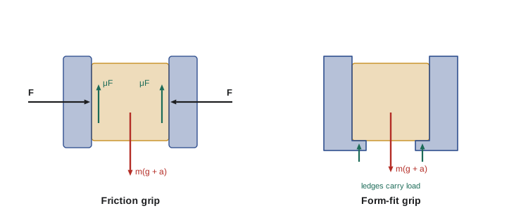
Consider a parallel-jaw gripper holding an object between two flat pads, with the load acting along the jaw faces, the most common case. Each jaw presses with normal force \( F_g \). The friction at each pad can carry at most \( \mu F_g \), so two pads together carry \( 2 \mu F_g \). For the grip to hold, that capacity must exceed the load, with a safety factor \( S \).
Here \( n \) is the number of friction surfaces carrying the load, two for a parallel-jaw pinch, and \( F_g \) is the grip force per jaw, which catalogs call the gripping force. Typical safety factors are 2 for steady, well-characterized loads and 3 to 4 when there are shocks, uncertain friction or high consequences of dropping. The equation makes the role of friction stark: halving \( \mu \) doubles the required grip force, which is why lesson 3 insisted on measuring it on the real product.
Worked problem
Grip force for a machined part
A steel part of 2.4 kg is picked by a parallel-jaw gripper with polyurethane pads. Tests give \( \mu \ge 0.30 \) between pad and oily steel. The robot accelerates the part upward at up to 6 m/s². Using a safety factor of 2.5, what grip force per jaw is needed?
Show solution
- Load: \( m(g + a) = 2.4 \times (9.81 + 6.0) = 37.9 \) N.
- Required grip force: \( F_g \ge \dfrac{37.9 \times 2.5}{2 \times 0.30} = 158 \) N per jaw.
- In pound-force: about \( 158 / 4.448 \approx 35.5 \) lbf.
- Pick a gripper whose rated grip force at the actual finger length and opening is at least 160 N; ratings fall as fingers get longer.
Answer: About 160 N per jaw. If the oil could be removed and \( \mu \) rose to 0.5, the requirement would fall to about 95 N, which shows how much process conditions drive gripper size.
Form-fit grips and finger length
If the jaws are shaped to cup the part, for example with a step under its edge or a V-groove around a cylinder, geometry carries much of the load. A V-groove with half-angle \( \theta \) multiplies the effective normal force on a cylinder: each jaw's grip force produces two contact normals, and the friction capacity rises roughly by a factor \( 1/\sin\theta \). Grippers with form-fit jaws often need a third to a half of the grip force of flat jaws, which allows a smaller gripper, faster closing and gentler handling. The trade-off is that each part shape needs its own jaws or adaptable fingers.
Finger length matters more than many designers expect. Catalog grip forces are quoted at a reference finger length; longer fingers place the contact farther from the gripper's guide, increasing the bending moment on the jaw bearings and, for many designs, reducing the available force. Manufacturers publish curves of allowable force against finger length and allowable moments on the jaws, and the sizing check must use them, not the headline number.
Worked problem
V-groove fingers for a cylinder
A 1.5 kg cylinder is held horizontally by jaws with V-grooves of half-angle \( 45^\circ \). With \( \mu = 0.25 \), acceleration 5 m/s² and safety factor 2.5, compare the grip force needed with flat jaws and with V-grooves.
Show solution
- Load: \( 1.5 \times (9.81 + 5) = 22.2 \) N.
- Flat jaws: \( F_g = 22.2 \times 2.5 / (2 \times 0.25) = 111 \) N per jaw.
- V-grooves multiply friction capacity by about \( 1/\sin 45^\circ \approx 1.41 \): \( 111 / 1.41 \approx 79 \) N per jaw.
- If the V-groove also supports the cylinder from below, geometry carries part of the weight directly and the required force falls further.
Answer: About 111 N with flat jaws and about 79 N with V-grooves, roughly a 30 % reduction, plus better centering of the part.
Suction cup holding force
A suction cup holds by pressure difference. The vacuum generator lowers the pressure inside the cup by \( \Delta p \) below atmospheric, and the atmosphere pushes the object against the cup with a force equal to \( \Delta p \) times the effective area \( A \) inside the seal. The theoretical holding force for a cup lifting straight up, with the cup above a horizontal surface, is \( F = \Delta p A \). Real cups deform, the seal area shrinks under load and the vacuum level varies, so designers divide by a safety factor and size for the worst orientation.
Three load cases recur. When the cup lifts vertically from above, the load acts along the cup axis, and the pressure force resists it directly. When the cup holds a part on a vertical face, the load acts across the cup, and only friction between the cup lip and the surface resists it: the required pressure force is the load divided by the lip friction coefficient, often about 0.5 for rubber on dry clean surfaces, so the cup must be about twice as strong. When the part swings during fast motion, the load combines both, and inertial forces can peel the cup off at one edge, which is why fast systems use more cups spaced apart.
# Suction cup sizing: diameter needed for a carton picked from above, then for a vertical face
import numpy as np
m, a, g = 3.0, 8.0, 9.81          # kg, peak acceleration m/s^2
dp = 60e3                          # usable vacuum, Pa (about -0.6 bar gauge)
S_vert, S_side, mu_lip = 2.0, 2.0, 0.5
load = m * (g + a)
def diameter(force):                # diameter giving dp * area = force
    return np.sqrt(4 * force / (np.pi * dp))
d_top = diameter(load * S_vert)
d_side = diameter(load * S_side / mu_lip)
for n in (1, 2, 4):
    print(f"{n} cup(s): from above d = {1000*d_top/np.sqrt(n):5.1f} mm each, on a vertical face d = {1000*d_side/np.sqrt(n):5.1f} mm each")
print(f"load {load:.1f} N ({load/4.448:.1f} lbf); vacuum {dp/1000:.0f} kPa ({dp/6895:.1f} psi)")1 cup(s): from above d = 47.6 mm each, on a vertical face d = 67.3 mm each 2 cup(s): from above d = 33.7 mm each, on a vertical face d = 47.6 mm each 4 cup(s): from above d = 23.8 mm each, on a vertical face d = 33.7 mm each load 53.4 N (12.0 lbf); vacuum 60 kPa (8.7 psi)
The output shows the cost of picking from the side: the same carton needs cups about 41 % larger in diameter, because \( \sqrt{1/0.5} \approx 1.41 \), and that is before considering peel. Splitting the force over several cups reduces each cup's size by the square root of the number of cups and, just as importantly, keeps the part from tilting if one cup leaks.
Vacuum levels, porous items and generators
The usable vacuum depends on the generator and on leakage. Venturi ejectors driven by compressed air are compact and fast, and typically reach 60 to 85 kPa of vacuum on sealed surfaces. Electric vacuum pumps and blowers are more energy-efficient for continuous use; blowers move large volumes at low vacuum, which suits porous items such as cardboard and fabric that leak air through the surface. For porous items the design question becomes flow: the generator must remove air as fast as it leaks in, and the achievable vacuum may be only 10 to 30 kPa. Sizing then relies on tests with the real material.
Vacuum switches and sensors measure the level inside the cup and confirm a grasp before the arm moves. A threshold set from tests, for example 70 % of the sealed vacuum level, distinguishes a good seal from a partial one. Many systems also add a check valve or a vacuum reservoir so that a brief loss of supply does not drop the part immediately, and a blow-off pulse to release it quickly at the place location.
Worked problem
Is the vacuum level enough?
A single 40 mm cup holds a 1.2 kg sealed box lifted from above with peak acceleration 5 m/s². The vacuum sensor reads 55 kPa during a test pick. Is the safety factor at least 2?
Show solution
- Cup area: \( \pi \times 0.040^2 / 4 = 1.26 \times 10^{-3} \) m².
- Pressure force: \( 55{,}000 \times 1.26 \times 10^{-3} = 69.1 \) N.
- Load: \( 1.2 \times (9.81 + 5) = 17.8 \) N.
- Safety factor: \( 69.1 / 17.8 \approx 3.9 \).
Answer: Yes, about 3.9 on paper. Because effective area under load is smaller than the nominal cup area, many designers use 70–80 % of nominal area, which still gives about 3.
Magnetic and other holding methods
Permanent electro-switchable magnets hold ferrous parts with forces that depend strongly on the part thickness, surface finish and air gap: a thin sheet saturates and holds far less than the catalog value measured on thick steel. Electroadhesion and gecko-inspired dry adhesives hold flat, smooth items such as glass and sheets with low power. Each method has its own sizing curves, but the logic is the same: the worst-case load, with a safety factor, must be less than the holding force under real surface conditions.
Protecting the object
Sizing has a ceiling as well as a floor. Grip force that holds a part comfortably may dent a thin aluminum housing, crack an egg or crush a soft package. Lesson 3 showed that spreading the force over a larger area lowers pressure. Electric grippers with force control let the designer set the grip force per item, and adaptive systems lower it for fragile items when the weight measured by a wrist sensor is low. For suction, high vacuum on thin film can pull it into the cup and tear it; lower vacuum with a larger cup holds the same load more gently.
Worked problem
Choosing between more force and a larger contact
A 0.4 kg pouch of granola must be picked with parallel jaws. With \( \mu = 0.6 \), \( a = 4 \) m/s² and \( S = 3 \), what grip force is needed? Its film tears above about 30 kPa average pressure. What minimum pad area per jaw is needed?
Show solution
- Load: \( 0.4 \times (9.81 + 4) = 5.5 \) N.
- Grip force: \( 5.5 \times 3 / (2 \times 0.6) = 13.8 \) N per jaw.
- Maximum pressure 30 kPa means area \( \ge 13.8 / 30{,}000 = 4.6 \times 10^{-4} \) m², or 460 mm² per jaw.
- A 25 mm by 25 mm soft pad gives 625 mm², a comfortable margin.
Answer: About 14 N per jaw, spread over at least about 460 mm²; soft pads of 25 mm by 25 mm or larger keep the pressure safe.
Verifying the design
Calculations give a starting point; tests confirm it. A standard qualification test lifts the heaviest item and runs the robot through its fastest motion profile repeatedly, often hundreds of cycles, while logging grip force or vacuum level and watching for slip with a camera or a marker on the part. Tests are repeated with contaminated surfaces, worn pads and the lowest expected supply pressure. The design is accepted only when it passes the worst conditions, not just the average ones.
Common mistakes
MistakeSizing for gravity alone
InsteadAdd the peak acceleration and process forces in the worst direction.
MistakeUsing the catalog grip force at any finger length
InsteadRead the allowable force and moments for the actual finger length and offset.
MistakeAssuming a suction cup holds a vertical face as well as it lifts from above
InsteadSide loads rely on lip friction; size cups about \( 1/\mu \) times stronger or pick from above.
MistakeIgnoring leakage on porous items
InsteadSize the generator for flow, test real materials and expect low vacuum levels.
MistakeRaising grip force until nothing slips
InsteadCheck pressure limits for fragile items and increase contact area instead.
Summary and key terms
- Sizing starts from the worst-case load: weight, acceleration and process forces in the most demanding direction.
- Friction grip force per jaw is \( F_g \ge m(g + a)S / (n\mu) \); friction and the safety factor dominate the result.
- Form-fit and V-groove jaws carry load through geometry and reduce the required grip force.
- Allowable grip force and jaw moments depend on finger length; use the manufacturer's curves.
- Suction holding force is \( \Delta p A / S \); side loads rely on lip friction and need larger or more cups.
- Porous items leak and need flow-rated generators; vacuum sensing confirms each grasp.
- Upper limits matter too: spread force over larger areas to protect fragile objects, then verify by testing.
- Grip force
- The normal force each jaw applies to the object.
- Safety factor
- A multiplier covering loads and uncertainties the model omits.
- Form-fit grip
- A grip in which jaw geometry carries the main load directly.
- V-groove jaw
- A jaw with a V-shaped notch that centers cylinders and increases friction capacity.
- Pressure difference
- The vacuum level \( \Delta p \) below atmospheric pressure inside a suction cup.
- Effective area
- The area inside a suction cup's seal over which the pressure difference acts.
- Venturi ejector
- A compressed-air device that creates vacuum through a fast air jet.
- Vacuum blower
- A high-flow, low-vacuum generator suited to porous items.
- Peel
- Loss of a suction seal starting at one edge under a tilting load.
- Blow-off
- A short pulse of air that releases a part from a suction cup.
Practice problems
Work each problem on paper first, then reveal the answer to check.
A 1 kg part, \( a = 0 \), \( \mu = 0.5 \), \( S = 2 \), two jaws. Grip force?
Show answer
About 19.6 N per jaw.
What happens to the required grip force if \( \mu \) halves?
Show answer
It doubles.
Convert 200 N to lbf.
Show answer
About 45 lbf.
Holding force of a 30 mm cup at 70 kPa, no safety factor?
Show answer
About 49.5 N.
Why do fast systems use several spaced cups?
Show answer
To resist tilting and peel and to tolerate a leaking cup.
A side-held part needs 40 N of friction with lip \( \mu = 0.5 \). Pressure force needed?
Show answer
80 N, before the safety factor.
Which generator suits porous cardboard?
Show answer
A high-flow blower or electric pump rather than a small venturi.
How does a check valve help?
Show answer
It holds vacuum briefly if the supply fails.
Pad area for 20 N at a 25 kPa limit?
Show answer
800 mm².
What does a qualification test add to calculations?
Show answer
Proof under worst conditions: fastest motion, contamination, worn pads and low supply.
Lesson quiz · 5 questions
Score 60% or more to complete this lesson.
Create a free account to save your progress, take quizzes and earn a certificate.