
ROB-320 · Lesson 7 of 12 · 30 min
Interrupts, shared data and DMA
Interrupts are where the outside world meets the software: an encoder edge, a finished ADC conversion, a CAN frame, a timer reaching its compare value. ROB-200 showed how to configure and enable them. This lesson is about their timing and their hazards in a system with many tasks: how long it takes from a hardware event to the first instruction of its handler, what can make that longer, how to share data between interrupt handlers and tasks without corrupting it, and how direct memory access (DMA) moves data without the processor so that interrupts can be fewer and shorter.
Anatomy of interrupt latency
Interrupt latency is the time from the hardware event to the start of useful work in its handler. Several pieces add up:
- Hardware recognition and synchronization: the peripheral raises its request and the interrupt controller registers it, usually a few clock cycles.
- Completion of the current instruction: most instructions finish in a cycle or two, but some (multi-word loads and stores, divides) take longer or are abandoned and restarted.
- Masking: if interrupts are disabled, or a higher- or equal-priority interrupt is running, the new one waits. This is usually the largest and most variable component.
- Entry overhead: saving registers and fetching the vector. On a Cortex-M3, M4 or M7 the hardware stacks eight registers and starts the handler in a fixed 12 cycles in the best case, plus more if floating-point state must be saved and the lazy stacking feature is off.
- Software preamble: anything the handler does before the time-critical step, such as reading a status register or calling into a driver layer.
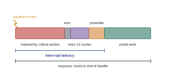
The masking term is controlled entirely by software design: the longest time anyone disables interrupts, and the longest handler at the same or higher priority, set the worst-case latency for every interrupt below them. A single driver that disables interrupts for 200 µs to copy a buffer adds 200 µs to the worst-case latency of every interrupt in the system.
Worked problem
Worst-case interrupt latency
On a 200 MHz Cortex-M7, the encoder interrupt has the highest priority. The longest critical section anywhere in the code disables interrupts for 3 µs. Hardware entry takes 12 cycles plus 18 more for lazy floating-point stacking; the handler preamble takes 40 cycles. What is the worst-case latency to useful work?
Show solution
- Masking: 3 µs.
- Entry: \( 12 + 18 = 30 \) cycles \( = 0.15 \) µs.
- Preamble: 40 cycles \( = 0.20 \) µs.
- Allow 10 cycles (0.05 µs) for the current instruction.
- Total: \( 3 + 0.15 + 0.20 + 0.05 = 3.4 \) µs.
Answer: About 3.4 µs, dominated by the 3 µs critical section. Shortening the longest interrupts-off section is almost always the most effective way to cut worst-case latency.
Interrupt priorities and nesting
Nested vectored interrupt controllers allow a higher-priority interrupt to preempt a lower-priority handler. Each interrupt's worst-case response time can therefore be analyzed with the same response-time equation used for tasks in lesson 5, treating each interrupt source as a sporadic task with a minimum inter-arrival time. Assign interrupt priorities by deadline: the encoder index pulse that must be captured within 2 µs outranks the UART receive that can wait 80 µs, which outranks the 1 kHz control timer whose work takes 100 µs. All interrupts outrank all RTOS tasks, so total interrupt load directly reduces the processor time available to tasks.
On Cortex-M processors running FreeRTOS, interrupts are split by a configuration value called configMAX_SYSCALL_INTERRUPT_PRIORITY. Interrupts more urgent than this level are never masked by the kernel, so they get the lowest possible latency, but they must not call any RTOS function. Interrupts at or below that level may call the FromISR functions, but the kernel masks them briefly in its own critical sections. Choosing which interrupts sit above the line is a real design decision: put the few truly time-critical, self-contained handlers above it, and everything that needs to wake a task below it.
Writing good interrupt handlers
Short, bounded handlers keep latency low for everyone. A good handler acknowledges the hardware, captures the time-critical data, and either finishes the job (if it is tiny) or hands off to a task. A rule of thumb used in many robot firmware teams is that no handler may run longer than about 10 % of the shortest deadline in the system.
/* ADC-complete interrupt: capture, timestamp, hand off to a task */
void ADC_IRQHandler(void)
{
    BaseType_t woken = pdFALSE;
    uint16_t raw = ADC1->DR;                 /* reading DR clears the flag  */
    uint32_t t   = DWT->CYCCNT;              /* timestamp at the source     */
    spsc_push(&adc_ring, raw, t);            /* lock-free, never blocks     */
    vTaskNotifyGiveFromISR(adc_task, &woken);
    portYIELD_FROM_ISR(woken);               /* switch now if task is higher */
}
Timestamping at the source, inside the interrupt, matters for estimation: the Kalman filters of ROB-310 need to know when a measurement was taken, not when a task got round to processing it. The portYIELD_FROM_ISR call asks the kernel to switch directly to the woken task when the handler exits, if that task has higher priority than the one interrupted, so the hand-off adds only a context switch rather than waiting for the next tick.
Sharing data with interrupts
Data shared between an interrupt handler and a task needs protection just as data shared between tasks does, but mutexes cannot be used because a handler must never block. The options are:
- Disable the relevant interrupt, or all interrupts, around the task's access. This is correct but adds to everyone's latency, so it is only for a few instructions.
- Use variables that the processor reads and writes atomically, such as an aligned 32-bit word on a 32-bit processor, for single values like a counter or a flag.
- Use lock-free structures: single-producer single-consumer ring buffers, double buffers and sequence counters (lesson 6).
The C keyword volatile has a narrow job here. It tells the compiler that a variable may change outside the normal flow of the program, so every access must actually read or write memory instead of using a cached register value. Without it, a loop waiting for an interrupt to set a flag may be optimized into an infinite loop that never re-reads the flag. Volatile does not make an access atomic and does not order accesses on multicore processors; it is necessary but not sufficient. For multi-word data and multicore systems, C11 atomics or explicit memory barriers are needed.
# A single-producer single-consumer ring buffer with power-of-two masking
class Ring:
    def __init__(self, size):
        assert size & (size - 1) == 0, "size must be a power of two"
        self.buf = [None] * size
        self.mask = size - 1
        self.head = 0          # written only by the producer (interrupt)
        self.tail = 0          # written only by the consumer (task)
        self.dropped = 0
    def push(self, item):      # producer side: never blocks
        if self.head - self.tail == len(self.buf):
            self.dropped += 1  # full: count and drop instead of waiting
            return False
        self.buf[self.head & self.mask] = item
        self.head += 1         # publish only after the data is written
        return True
    def pop(self):             # consumer side
        if self.tail == self.head:
            return None
        item = self.buf[self.tail & self.mask]
        self.tail += 1
        return item

r = Ring(8)
for burst in range(3):
    for k in range(5):                 # interrupt delivers 5 samples
        r.push((burst, k))
    got = [r.pop() for k in range(3)]  # task keeps up with only 3
    print("burst", burst, "consumed", got, "backlog", r.head - r.tail)
print("dropped samples:", r.dropped)burst 0 consumed [(0, 0), (0, 1), (0, 2)] backlog 2 burst 1 consumed [(0, 3), (0, 4), (1, 0)] backlog 4 burst 2 consumed [(1, 1), (1, 2), (1, 3)] backlog 5 dropped samples: 1
Because each index is written by only one side, and the producer updates the head only after the data is in place, the consumer never sees a slot that is half-written. When the consumer cannot keep up, the buffer fills and the producer drops new samples and counts them, rather than blocking inside an interrupt. A non-zero drop counter is a design signal: either the buffer is too small for the worst burst or the consuming task's priority or rate is too low.
Worked problem
Sizing a ring buffer for a burst
A CAN interrupt can deliver up to 14 frames in 1 ms during a burst. The consuming task runs every 2 ms and can process 20 frames per run, but may be delayed by up to 1.5 ms by higher-priority work. How many slots does the ring need?
Show solution
- Worst time between consumer runs: \( 2 + 1.5 = 3.5 \) ms.
- Frames that can arrive in 3.5 ms at the burst rate: \( 14 \times 3.5 = 49 \).
- Round up to a power of two with margin: 64 slots.
Answer: Use 64 slots. Bursts of 14 frames per millisecond rarely last long, but sizing for the worst gap between consumer runs at the burst rate is the safe assumption.
Direct memory access
A DMA controller moves data between peripherals and memory without the processor, triggered by the peripheral. Instead of one interrupt per ADC sample or per received byte, the DMA fills a whole buffer and raises a single interrupt when it is half full and again when it is full. This cuts interrupt load dramatically and makes sampling timing independent of software latency, because the hardware timer triggers the ADC and the DMA stores each result as soon as it is ready.
The standard pattern is a circular buffer with half-transfer and transfer-complete interrupts, a form of double buffering: while the DMA fills the second half, software processes the first half, and vice versa. The software deadline is then half a buffer's duration, which is much more forgiving than one sample period.
Worked problem
Interrupt load with and without DMA
A force sensor is sampled at 10 kHz. Handling one sample per interrupt costs 2.5 µs. With DMA into a 64-sample circular buffer, each half-buffer interrupt costs 12 µs. Compare the interrupt loads and the processing deadline.
Show solution
- Per-sample interrupts: \( 10{,}000 \times 2.5 \) µs = 25 ms per second, a 2.5 % load, with a 100 µs deadline per sample.
- DMA: an interrupt every 32 samples, \( 10{,}000/32 = 312.5 \) per second, \( 312.5 \times 12 \) µs = 3.75 ms per second, a 0.375 % load.
- Processing deadline with DMA: half a buffer, \( 32/10{,}000 = 3.2 \) ms.
Answer: DMA cuts the interrupt load from 2.5 % to under 0.4 % and relaxes the processing deadline from 100 µs to 3.2 ms, at the cost of 3.2 ms of extra latency before a sample is processed. For a 1 kHz force loop that latency is too much, so a smaller buffer (8 samples, 0.4 ms) would be chosen.
DMA brings its own hazards. On processors with data caches, such as the Cortex-M7 and application processors, the processor may hold stale copies of a buffer the DMA has just written, or the DMA may read memory before the processor's cached writes reach it. The fixes are to place DMA buffers in non-cacheable memory, or to clean and invalidate the cache over the buffer at the right moments. DMA also competes with the processor for the memory bus, which can stretch execution times, another reason to measure WCET under full load.
Interrupt storms and protection
A faulty sensor, a noisy encoder line or a misconfigured peripheral can fire interrupts far faster than designed, starving every task below. Defensive firmware bounds this: count interrupts per period and disable a source that exceeds its expected rate, filter noisy digital inputs in hardware, and use minimum inter-arrival enforcement for sporadic events so that the response-time analysis of lesson 5 remains valid. An emergency-stop input should be handled by hardware first (lesson 11), with software monitoring, so that an interrupt problem cannot delay a safety stop.
| Problem | Symptom | Defense |
|---|---|---|
| Long interrupts-off section | Large, rare latency spikes on all interrupts | Find with a trace; shorten or replace with lock-free code |
| Handler doing slow work | Lower interrupts and tasks starve | Defer to a task; set a handler time budget |
| Missing volatile on a shared flag | Loop never sees the flag change at higher optimization | Declare shared variables volatile, use atomics |
| Stale DMA buffer in cache | Old or corrupted data, only with caches enabled | Non-cacheable buffers or cache maintenance |
| Interrupt storm from a noisy input | System appears to hang | Rate limiting, hardware filtering, input debouncing |
Common mistakes
MistakeDisabling all interrupts around long operations
InsteadDisable only for a few instructions and use lock-free structures for larger data.
MistakeCalling blocking RTOS functions from an interrupt
InsteadUse interrupt-safe calls and defer blocking work to a task.
MistakeAssuming volatile makes an access atomic
InsteadUse atomics, interrupt masking or lock-free patterns for multi-step updates.
MistakeTimestamping a sample when the task processes it
InsteadTimestamp in the interrupt or by hardware at the moment of capture.
MistakeUsing DMA buffers in cached memory without maintenance
InsteadPlace buffers in non-cacheable memory or clean and invalidate the cache.
Summary and key terms
- Interrupt latency is the sum of masking time, instruction completion, hardware entry and software preamble.
- The longest interrupts-off section and the longest equal or higher-priority handler dominate worst-case latency.
- Interrupts can be analyzed as sporadic highest-priority tasks and should be prioritized by deadline.
- Good handlers acknowledge, capture, timestamp and hand off to a task quickly.
- Data shared with interrupts needs brief masking, atomic variables or lock-free buffers, never mutexes.
- volatile prevents the compiler caching a variable but does not make accesses atomic.
- DMA with circular double buffers cuts interrupt load and relaxes deadlines, but needs cache coherence care.
- Interrupt latency
- Time from a hardware event to the start of useful work in its handler.
- Interrupt service routine
- The handler function the processor runs when an interrupt occurs.
- Nested interrupts
- Higher-priority interrupts preempting lower-priority handlers.
- Masking
- Temporarily preventing interrupts from being taken.
- volatile
- A C qualifier that forces every access to a variable to go to memory.
- Atomic variable
- A variable read or written in one indivisible operation.
- Ring buffer
- A circular array with head and tail indices used as a queue.
- DMA
- Direct memory access: hardware that moves data without the processor.
- Half-transfer interrupt
- A DMA interrupt raised when a circular buffer is half full.
- Cache coherence
- Keeping cached copies of memory consistent with what other bus masters see.
Practice problems
Work each problem on paper first, then reveal the answer to check.
Name the largest usual contributor to worst-case interrupt latency.
Show answer
Time spent with interrupts masked or in higher-priority handlers.
A critical section of 5 µs exists. What is the minimum worst-case latency for any interrupt?
Show answer
At least 5 µs.
How many cycles does Cortex-M hardware entry take at best?
Show answer
12 cycles.
Why timestamp inside the interrupt?
Show answer
So estimators know when the measurement was taken.
Can an interrupt handler take a mutex?
Show answer
No; it must never block.
What does volatile guarantee?
Show answer
Each access really reads or writes memory.
In an SPSC ring, who writes the head index?
Show answer
Only the producer.
A 20 kHz sample stream uses a 128-sample circular DMA buffer. How often are half-transfer interrupts?
Show answer
Every 3.2 ms (312.5 per second).
Why must DMA buffers be non-cacheable or maintained on a Cortex-M7?
Show answer
The cache may hold stale copies.
Give one defense against an interrupt storm.
Show answer
Rate-limit and disable a source that exceeds its expected rate.
Lesson quiz · 5 questions
Score 60% or more to complete this lesson.
Create a free account to save your progress, take quizzes and earn a certificate.