
RAC-410 · Lesson 3 of 12 · 19 min
Centrifugal chillers in depth
In late April, on a mild night, CH-1 tripped. The operator on duty heard it first: a deep, rhythmic roar from the compressor, a few seconds of noise that rose and fell like a wave hitting a wall, then the machine shut down on a high discharge temperature alarm. He restarted it, and twenty minutes later it did the same thing. By the time Raj and Theo arrived in the morning, the operators had switched to CH-3 and left CH-1 off. Raj listened to the description and nodded. "That's surge," he said. "The question is why it surged last night and not all winter."
This lesson looks inside the centrifugal chiller: how its compressor works, what surge is and how it is prevented, how capacity is controlled with inlet vanes and variable-speed drives, the low-pressure refrigerants and the purge units they need, and the machine-room safety requirements that apply to large refrigerant charges.
How a centrifugal compressor works
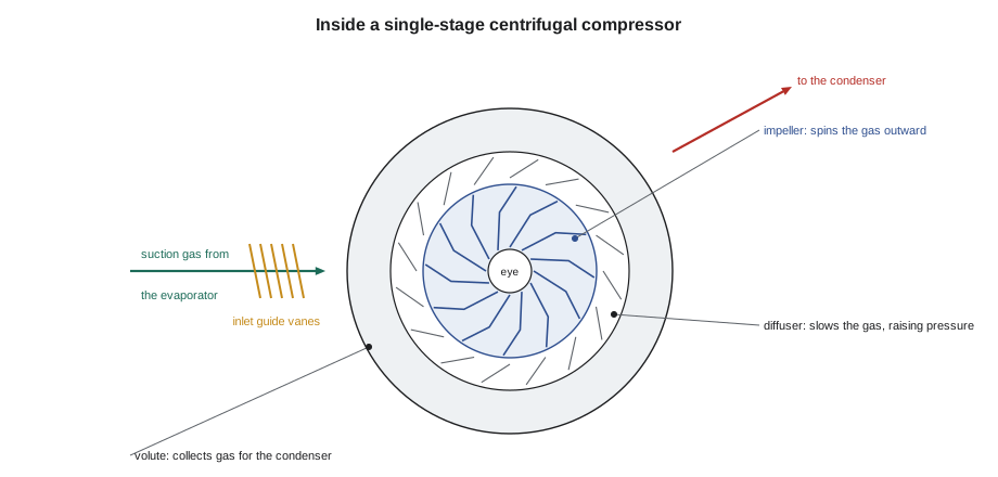
A centrifugal compressor is a dynamic machine. It does not trap a pocket of gas and squeeze it, as a reciprocating, scroll or screw compressor does. Instead, refrigerant vapor from the evaporator enters the eye of a rapidly spinning impeller, is flung outward by the blades and leaves the impeller tip at high velocity. Around the impeller, a diffuser, a ring of widening passages, slows the gas down, converting its velocity into pressure, and a spiral volute collects it and sends it to the condenser. Many machines have two or three impellers in series, each adding part of the pressure rise, sometimes with an economizer that feeds flash gas from an intermediate pressure into the second stage, improving efficiency.
The impeller turns fast: typically several thousand to more than twenty thousand revolutions per minute, driven by a motor through a speed-increasing gear or, in some designs, directly by a high-speed motor. Many modern centrifugals use magnetic bearings, which levitate the shaft in a magnetic field, so the compressor needs no oil at all; others have conventional bearings with an oil pump, oil cooler, oil heater and oil reservoir. The pressure a centrifugal compressor can produce depends on the speed of its impeller tip. It cannot simply push harder, as a positive-displacement compressor can; at a given speed there is a maximum pressure rise it can develop.
Lift and surge
The pressure rise a chiller's compressor must produce is set by the difference between its condensing and evaporating pressures, which in turn are set by the temperatures. Plant engineers usually express it as lift, the difference between the condenser saturation temperature and the evaporator saturation temperature. Lift rises when the condenser water is warmer, when the chilled water is colder and when the heat exchangers are fouled, because each of these widens the gap between the two saturation temperatures.
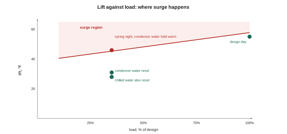
Surge happens when the compressor is asked for more lift than it can develop at the flow it is passing. At low flow, the gas leaving the impeller cannot keep up the pressure against the condenser; the flow stalls and briefly reverses, gas rushes back from the condenser through the compressor, the condenser pressure drops, the compressor picks up again and the cycle repeats, several times a second or more slowly, with the roar the operator heard. Surge overheats the compressor, hammers the bearings, impeller and seals and can destroy a machine if it continues. Every centrifugal chiller's controls watch for it, by sensing the motor current swings, the pressure fluctuations or the discharge temperature rise, and shut the machine down or take corrective action.
The danger zone is high lift at low load. A constant-speed centrifugal at full load has a comfortable margin, because the flow is high. At low load the flow through the impeller is small, the surge limit is lower, and if the condenser water stays warm, the lift does not fall with the load. That is a common situation on a spring night in a plant whose towers are controlled to hold the condenser water at a fixed temperature: the load is low, but the condenser water is still at its summer setpoint.
Capacity control: inlet vanes and variable speed
A constant-speed centrifugal controls its capacity with inlet guide vanes, adjustable vanes in the suction inlet that pre-swirl the gas in the direction of rotation. Closing them reduces the flow and the work the impeller does on the gas. They work well down to perhaps 30 or 40 % of capacity, but the machine's efficiency falls at low load and its surge margin shrinks, as CH-1's ratings in lesson 2 showed. Some machines add a variable diffuser or a hot-gas bypass to stay out of surge at very low loads, at the cost of efficiency.
A variable-speed drive changes the impeller speed. Because the head a centrifugal can develop rises roughly with the square of its speed, the drive can slow the compressor whenever the lift is low, which is most of the year, and the power falls sharply. The controls choose a combination of speed and vane position that delivers the load at the lowest power while staying clear of surge. When the lift is high, they must keep the speed up even at low load. That is why a variable-speed chiller's savings depend on cold condenser water: without it, the drive cannot slow down very far.
Raj laid out the night CH-1 had tripped. The load was about 35 % of the plant's design. The towers were holding the condenser water at their summer setpoint of 85 °F, because nobody had enabled the condenser water reset after the controls upgrade the year before. The script estimates CH-1's lift and compares it with a simplified surge limit for its vane-controlled compressor; it also estimates the speed CH-2's drive would need for the same lift.
import math
# lift = condenser saturation temperature - evaporator saturation temperature (temperatures in F)
def lift(chw_supply, cw_enter, load, cw_range=10.0, evap_app=2.0, cond_app=2.0):
    t_evap = chw_supply - evap_app * load              # approaches shrink at part load
    t_cond = cw_enter + cw_range * load + cond_app * load
    return t_cond - t_evap
design = lift(44.0, 85.0, 1.0)
print(f"design lift {design:.1f} F")
cases = [("design day, full load", 44.0, 85.0, 1.0), ("spring night, 35 % load, towers held 85 F", 44.0, 85.0, 0.35),
         ("spring night, 35 % load, condenser water reset to 70 F", 44.0, 70.0, 0.35),
         ("same, chilled water also reset to 47 F", 47.0, 70.0, 0.35)]
for name, chws, cw, load in cases:
    L = lift(chws, cw, load)
    limit = design * (0.70 + 0.35 * load)           # simplified surge line for the vane-controlled CH-1
    speed = max(0.70, math.sqrt(L / design))         # CH-2: head rises with speed squared; drive floor 70 %
    flag = "SURGE RISK" if L > limit else "ok"
    print(f"{name:50s} lift {L:4.1f} F | CH-1 limit {limit:4.1f} F {flag:10s} | CH-2 speed {speed:.0%}")
# purge check on CH-2 (R-1233zd(E)): pressure above saturation means non-condensable gas in the condenser
def p_sat(tf):                                        # psia, approximate fit through 65 F at 14.7 psia and 77 F at 18.8 psia
    t = (tf - 32) / 1.8 + 273.15
    return 14.696 * math.exp(-3212 * (1 / t - 1 / 291.45))
t_liquid, p_read = 93.0, 29.7                        # psia at the condenser, liquid leaving at 93 F
excess = p_read - p_sat(t_liquid)
print(f"saturation at {t_liquid:.0f} F about {p_sat(t_liquid):.1f} psia; reading {p_read:.1f}; excess {excess:.1f} psi of non-condensables")
print(f"evaporator at 40 F is about {p_sat(40):.1f} psia, below the 14.7 psia atmosphere: leaks let air in")design lift 55.0 F design day, full load lift 55.0 F | CH-1 limit 57.7 F ok | CH-2 speed 100% spring night, 35 % load, towers held 85 F lift 45.9 F | CH-1 limit 45.2 F SURGE RISK | CH-2 speed 91% spring night, 35 % load, condenser water reset to 70 F lift 30.9 F | CH-1 limit 45.2 F ok | CH-2 speed 75% same, chilled water also reset to 47 F lift 27.9 F | CH-1 limit 45.2 F ok | CH-2 speed 71% saturation at 93 F about 25.7 psia; reading 29.7; excess 4.0 psi of non-condensables evaporator at 40 F is about 8.5 psia, below the 14.7 psia atmosphere: leaks let air in
The design lift was about 55 °F. On the spring night, with the condenser water held at 85 °F, the lift at 35 % load was still about 46 °F, just above CH-1's simplified surge limit at that load. Resetting the condenser water to 70 °F dropped the lift to about 31 °F, well clear of the limit; raising the chilled water to 47 °F as well, when the hospital's humidity allowed, dropped it further. CH-2's drive, in the same conditions, would run at about 75 % speed instead of 91 %.
The cause was a setting, not a failure. The tower controls were set to reset the condenser water with the wet bulb, down to a minimum the chillers allowed, and CH-1 was put back in service with a staging rule that kept it off at low loads. The surge limit in the script is a simplified line for teaching; a real machine's surge map comes from the manufacturer, and the chiller's controls use their own surge protection. But the lesson is general: high lift at low load is the condition to avoid, and the condenser water temperature is the easiest lever.
Low-pressure refrigerants and purge units
Centrifugal chillers have used two families of refrigerants. Medium- and high-pressure ones, such as R-134a in CH-1 and the newer R-513A and R-1234ze(E), run above atmospheric pressure on both sides. Low-pressure refrigerants, historically R-11 and R-123 and now R-1233zd(E) and R-514A, boil at around room temperature at atmospheric pressure, so the evaporator of a chiller using them runs below atmospheric pressure, in a vacuum. CH-2 used R-1233zd(E), a refrigerant with a global warming potential of about 1, safety class A1, and a normal boiling point of about 65 °F.
A machine with part of its system in a vacuum leaks inward. Air and moisture enter through any small leak, collect in the condenser, where they cannot condense, and raise the condensing pressure, which adds lift and wastes energy. Moisture also forms acids with the refrigerant and oil. Low-pressure chillers therefore have a purge unit: a small refrigeration system that draws vapor from the top of the condenser, condenses the refrigerant out of it and returns the refrigerant to the chiller, venting the non-condensable gas, which modern high-efficiency purges do with very little refrigerant loss. The purge's run time is a leak indicator: a purge that runs much more than usual is pumping out air that is getting in somewhere, and the operator should log it daily, as lesson 10 describes.
A pressure check shows non-condensables directly. With the machine off and the water circulating long enough for the condenser to reach a steady temperature, or in operation by comparing the condenser pressure with the saturation pressure at the leaving liquid temperature, any excess pressure is the partial pressure of gas that will not condense. The script's second part does that check on CH-2. The reading was about 4 psi above the saturation pressure at the liquid temperature, far more than a well-purged machine shows, and the evaporator, at about 8.5 psia, was well below atmospheric. A leak test found the source at a loose sight-glass fitting; the purge cleared the air over the following day.
Medium-pressure machines leak outward instead. They lose refrigerant rather than gaining air, so their leak indicators are the refrigerant level in the sight glass or the level sensor, the subcooling, the room's refrigerant monitor and the leak inspections that lesson 11 describes.
Machine rooms and refrigerant safety
A chiller room holds hundreds of kilograms of refrigerant. RAC-210 and RAC-220 introduced the safety standards; for large machines, the machine-room requirements are the important part. ASHRAE 15, Safety Standard for Refrigeration Systems, as adopted through the mechanical code, requires a machinery room for systems of this size, with:
- Refrigerant detectors that sense a leak at or below the refrigerant's occupational exposure limit and sound alarms inside and outside the room.
- Mechanical ventilation, switched on by the detector and by a manual switch outside the door, sized to the room and the largest charge.
- Relief valve or rupture disc discharges piped to outdoors away from openings, so that a relief event does not fill the room.
- Tight-fitting, self-closing doors, restrictions on open flames and combustion equipment in the room, and signs identifying the refrigerant and its safety class.
- A self-contained breathing apparatus or other emergency equipment as the standard and the owner's emergency plan require.
At Riverbend, the machine room had a multi-point refrigerant monitor with sample points near each chiller and at the floor, because the vapor of both refrigerants is heavier than air and settles. Part of Northfield's contract was to calibrate the monitor and test the ventilation interlock twice a year. Theo learned to read its log of low-level alarms too, because a monitor that records small, repeated readings near one chiller is often the first sign of a small leak. Lesson 11 returns to leak management and records.
Common mistakes
MistakeTreating a surge trip as a compressor failure.
InsteadLook first at lift and load: warm condenser water at low load is the usual cause.
MistakeHolding condenser water at its summer setpoint all year.
InsteadReset it with the wet bulb, down to the minimum the chiller allows.
MistakeIgnoring purge run time on a low-pressure chiller.
InsteadLog it daily; a rising run time means air is leaking in.
MistakeAssuming a variable-speed drive saves energy in every condition.
InsteadIt saves most when lift is low; at high lift it must run fast.
MistakeDisabling a refrigerant monitor alarm that keeps sounding.
InsteadInvestigate repeated low-level alarms; they often point to a leak.
Summary and key terms
- A centrifugal compressor raises pressure by accelerating gas in an impeller and slowing it in a diffuser.
- Lift is the condenser saturation temperature minus the evaporator saturation temperature.
- Surge is flow reversal when the compressor cannot develop the lift at the flow it passes; it is most likely at low load and high lift.
- Inlet guide vanes control capacity at constant speed; variable-speed drives save energy by slowing the impeller when lift is low.
- Low-pressure refrigerants run the evaporator in a vacuum, so air leaks in and purge units remove it; purge run time is a leak indicator.
- Machinery rooms need refrigerant detectors, ventilation, relief discharge to outdoors and other safeguards under ASHRAE 15.
- Impeller
- The rotating wheel that accelerates refrigerant gas in a centrifugal compressor.
- Diffuser
- The passage around the impeller that converts gas velocity into pressure.
- Lift
- The difference between condenser and evaporator saturation temperatures.
- Surge
- Unstable flow reversal in a centrifugal compressor at high lift and low flow.
- Inlet guide vanes
- Adjustable vanes at the compressor inlet that control capacity.
- Purge unit
- A device that removes non-condensable gases from a low-pressure chiller.
- Non-condensables
- Air and other gases in a refrigeration system that do not condense at its operating conditions.
- Machinery room
- A room for refrigeration equipment meeting the safety standard’s ventilation, detection and other requirements.
Practice problems
Work each problem on paper first, then reveal the answer to check.
Name three things that increase a chiller's lift.
Show answer
Warmer condenser water, colder chilled water, and fouled heat exchanger tubes.
Why is a centrifugal more likely to surge at low load?
Show answer
The flow through the impeller is low, so the lift it can develop is lower, while warm condenser water may keep the required lift high.
A low-pressure chiller's purge is running three times longer than last month. What does it suggest?
Show answer
Air is leaking into the vacuum side; leak test the machine.
Where should refrigerant monitor sample points be placed for refrigerants heavier than air?
Show answer
Low in the room, near the chillers, where vapor will collect.
Lesson quiz · 5 questions
Score 60% or more to complete this lesson.
Create a free account to save your progress, take quizzes and earn a certificate.