
PET-380 · Lesson 9 of 12 · 18 min
Pipeline and gathering system design
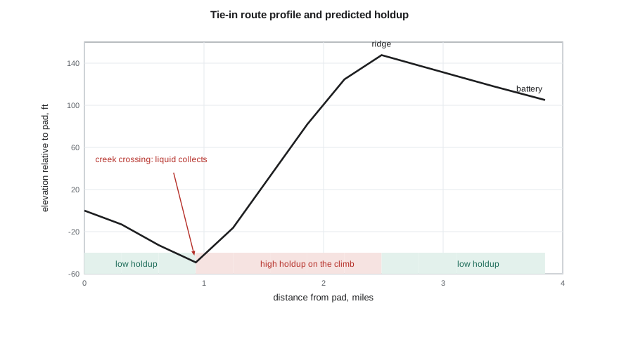
The 4-22H pad is scheduled to be drilled next year, and Sofia gives Ethan his first design task: a preliminary sizing for its tie-in line to the Tamarack pad facility. Lena, the surveyor who walked the route last spring, shows him the profile on the screen. The line runs 3.9 miles from the pad, drops to a creek crossing, climbs a long ridge and then descends gently to the facility, which sits 105 ft higher than the pad. 'You will have to justify the size, the wall thickness and the route to the regulators,' Sofia says, 'and to the operators, who will live with it for twenty years.'
This lesson sets out the main steps of multiphase gathering line design: defining the design basis, sizing by pressure drop and velocity, checking erosional limits, selecting the wall thickness from the governing code, and accounting for terrain, networks and regulatory requirements.
The design basis
Every design starts with a written basis. It records the fluids (oil, gas and water compositions, gas-oil ratio and water cut, contaminants such as carbon dioxide, hydrogen sulfide and sand), the production profile over the life of the field, the arrival pressure required at the facility, the maximum pressure the wells or upstream equipment can deliver, the route and elevation profile, ground temperatures, and the design life. The production profile is especially important for multiphase lines, because the flow pattern, holdup and pressure drop can change completely between the first and the last year of operation.
For the 4-22H pad, Tom's forecast gives an initial rate of about 6,900 bbl/d of in-situ liquid and 184,000 ft³/d of in-situ gas at line conditions, falling to about a quarter of that by year ten. The inlet separator at the facility operates at 102 psig, and the pad wellheads can deliver up to about 290 psig while the wells are young.
Sizing by pressure drop
The first sizing check is pressure drop. For each candidate diameter, the engineer computes the pressure drop at the design rates with a method validated as in lesson 7, and compares it with the available pressure: the difference between what the wells can deliver and what the facility needs. A smaller pipe costs less but has more friction; a larger pipe costs more and, at low rates, holds up more liquid on the uphill sections. Because the gravity and friction terms trade off against each other as diameter changes, the total pressure drop of a hilly multiphase line can have a minimum at some intermediate size, unlike single-phase lines where bigger is always lower.
# Gathering line design: size by pressure drop and velocity, check erosional velocity and wall thickness
import math
SI = False
g = 9.81
L, climb = 6200.0, 32.0                  # m route length, m net rise toward the battery
qL, qG = 900.0 / 86400, 4000.0 / 86400  # m3/s in-situ liquid and gas (average conditions)
rhoL, rhoG, muL = 880.0, 15.0, 0.003
def line(D, eps=4.6e-5):
    A = math.pi * D * D / 4
    vsl, vsg = qL / A, qG / A; vm = vsl + vsg; lam = vsl / vm
    HL = min(0.98, max(lam, 0.98 * lam ** 0.4846 / (vm * vm / (g * D)) ** 0.0868))   # Beggs-Brill segregated, horizontal
    rho_ns = rhoL * lam + rhoG * (1 - lam); rho_s = rhoL * HL + rhoG * (1 - HL)
    Re = rho_ns * vm * D / (muL * lam + 1.2e-5 * (1 - lam))
    f = 0.25 / math.log10(eps / D / 3.7 + 5.74 / Re ** 0.9) ** 2
    dpf = f * rho_ns * vm * vm / (2 * D) * L / 1000
    dpe = rho_s * g * climb / 1000
    rho_lbft3 = rho_ns * 0.062428
    ve = 100 / math.sqrt(rho_lbft3) * 0.3048        # API RP 14E with C = 100, converted to m/s
    return vm, dpf, dpe, ve
fp, up = (1, "kPa") if SI else (0.145038, "psi")
fv, uv = (1, "m/s") if SI else (3.2808, "ft/s")
for nps, D in (("4-inch", 0.1023), ("6-inch", 0.1541), ("8-inch", 0.2027)):
    vm, dpf, dpe, ve = line(D)
    print(f"{nps}: vm {vm * fv:5.2f} {uv}, friction {dpf * fp:5.0f} {up}, elevation {dpe * fp:4.0f} {up}, total {(dpf + dpe) * fp:5.0f} {up}, erosional limit {ve * fv:4.1f} {uv}")
# Design pressure from the hoop-stress (Barlow-type) formula with a design factor
S = 359e6                               # Pa, specified minimum yield strength (Grade 359 / X52)
Dout, t = 0.1683, 0.0048                # m, 6-inch NPS outside diameter, 4.8 mm wall
F = 0.8 if SI else 0.72                 # design factor used in this example for each code
P = 2 * S * t / Dout * F / 1000         # kPa
print(f"design pressure of 168.3 mm x 4.8 mm Grade 359 pipe with F = {F}: {P:6.0f} kPa" if SI else
f"design pressure of 6.625 in x 0.188 in X52 pipe with F = {F}: {P * 0.145038:5.0f} psig")4-inch: vm 22.64 ft/s, friction 673 psi, elevation 13 psi, total 686 psi, erosional limit 30.4 ft/s 6-inch: vm 9.98 ft/s, friction 87 psi, elevation 15 psi, total 102 psi, erosional limit 30.4 ft/s 8-inch: vm 5.77 ft/s, friction 22 psi, elevation 17 psi, total 39 psi, erosional limit 30.4 ft/s design pressure of 6.625 in x 0.188 in X52 pipe with F = 0.72: 2138 psig
At average design rates the 4-inch line loses nearly 690 psi, far beyond what the wells can deliver. The 6-inch line loses about 100 psi, and the 8-inch about 40 psi. The elevation component rises as the pipe gets larger, from 13 to 17 psi, because the slower flow holds up more liquid on the climbs. 'The 8-inch looks best now,' Sofia says, 'but look at the elevation term. That is the trend that will hurt in year ten.' Lesson 12 completes this comparison over the full production profile.
Velocity limits
Multiphase lines have both upper and lower velocity limits. The upper limit protects against erosion, noise and vibration. The most widely quoted guideline is from API Recommended Practice 14E, which gives an erosional velocity:
where ρ_m is the mixture density in lb/ft³, v_e is in ft/s, and C is an empirical constant, typically 100 for continuous service and 125 for intermittent service in sand-free fluids. The guideline is conservative for clean fluids and not conservative enough when sand is present, and API RP 14E itself suggests lower values where solids are expected. More rigorous erosion models, such as those of DNV and the Erosion/Corrosion Research Center at the University of Tulsa, estimate the metal loss rate from sand rate, particle size, velocity and pipe geometry, and are preferred for sandy production.
The lower limit is less formal. Below a mixture velocity of roughly 1 m/s (3 ft/s), many multiphase lines stop sweeping liquid from low spots and uphill sections, water and solids settle, and corrosion and pigging problems grow. Designers try to keep the late-life velocity above this range on the critical uphill sections, or plan for regular pigging if they cannot.
Wall thickness and design pressure
In the United States, gas pipelines, including regulated gas gathering lines, are designed to 49 CFR Part 192, and hazardous liquid lines, including regulated crude oil gathering lines, to 49 CFR Part 195. The design pressure for steel pipe follows a hoop-stress formula with several factors:
Here S is the specified minimum yield strength, t the nominal wall thickness, D the outside diameter, F the design factor, which depends on the class location (0.72 for Class 1 in Part 192), E the longitudinal joint factor and T the temperature derating factor. Ethan's code applies the formula to 6.625 in by 0.188 in X52 pipe, giving a design pressure of about 2,140 psig for a Class 1 location. That is far above the operating pressure, so the wall thickness will be set by corrosion allowance, handling and construction needs rather than by internal pressure.
Gathering lines often carry sour gas, produced water and sand, so the material selection also considers internal corrosion (lesson 11), sour service requirements for hydrogen sulfide, and whether non-metallic pipe, such as reinforced composite or spoolable pipe, would suit the pressure, temperature and fluid. Non-metallic lines are now common for produced water and lower-pressure oil gathering, because they do not corrode internally.
Terrain and route
The route affects both cost and hydraulics. Lesson 6 showed that on hilly terrain, the elevation losses on uphill sections are not recovered on downhills, and lesson 4 showed that small uphill angles promote slugging. A route that follows a ridge line or avoids deep valleys can reduce both holdup and terrain slugging. Low points at creek crossings collect water and solids, and become the most likely sites of internal corrosion. Designers often place pig launchers and receivers at the ends of each segment so the whole line can be pigged, and avoid fittings, reduced bores and tight bends that would block a pig.
Networks and gathering systems
A gathering system is a network of lines, each carrying production from one or more wells or pads into a trunk line or directly to a facility. A change in one part of the network affects the pressures, and therefore the rates, everywhere else. Adding the 4-22H pad to the existing line, for example, would raise the back pressure on the north pad wells. Network models solve the pressure and flow balances at every junction simultaneously, coupling the wells' inflow performance with the line hydraulics; this is the gathering-system extension of the nodal analysis Ethan used in production engineering. They are used to decide where to add new lines, whether to loop an existing line, where compression would be most effective, and how to allocate production when the facility is constrained.
Regulatory requirements
In the United States, federal rules depend on the substance and location. Gas gathering lines have been subject to an expanded federal regime since PHMSA's 2021 gas gathering final rule, which created Type C gathering lines in rural Class 1 locations, subject to selected safety requirements such as damage prevention, emergency planning and public awareness, depending on their diameter and operating stress, and Type R lines, which must file incident and annual reports. Regulated rural hazardous liquid gathering lines fall under Part 195. In North Dakota, the Industrial Commission's rules for underground gathering pipelines that carry crude oil or produced water, in North Dakota Administrative Code section 43-02-03-29.1, add state requirements for registration, construction and testing, leak detection and records. Lines carrying hydrogen sulfide face additional state and federal requirements.
From preliminary to detailed design
Preliminary sizing narrows the choices to one or two candidates. Detailed design then adds the transient and flow assurance studies of lessons 10 and 11: hydrate and wax risk during normal operation and after shutdown, slug sizes for the slug catcher or inlet separator, pigging frequency and pig slug volumes, corrosion allowance and inhibition, and the effects of start-up and turndown. The design is documented in a basis-of-design report that the operating team, the regulator and future engineers can read, and the assumptions it records, especially the production profile, should be revisited as actual production data arrive.
Worked problem
Design pressure of the candidate line
Using the 49 CFR 192.105 formula with S = 52,000 psi, t = 0.188 in, D = 6.625 in, F = 0.72 and E = T = 1.0, find the design pressure.
Show solution
- 2 S t / D = 2 × 52,000 × 0.188 / 6.625 = 2,951 psi.
- Multiply by F × E × T = 0.72 × 1.0 × 1.0 = 0.72.
- P = 2,951 × 0.72 = 2,125 psig.
Answer: About 2,125 psig, many times the planned operating pressure of about 290 psig.
Common mistakes
MistakeSizing a multiphase line only on initial rates.
InsteadCheck the whole production profile; late-life holdup can dominate.
MistakeAssuming a larger pipe always lowers pressure drop.
InsteadOn hilly terrain, a larger pipe can raise the elevation loss at low rates.
MistakeApplying the API RP 14E limit to sandy fluids unchanged.
InsteadUse a lower constant or a sand erosion model when solids are present.
MistakeDesigning a line that cannot be pigged.
InsteadProvide launchers and receivers and avoid fittings that block a pig.
Summary and key terms
- Design starts with a written basis: fluids, production profile, pressures, route and design life.
- Candidate sizes are compared by pressure drop at design rates over the field life.
- Upper velocity limits protect against erosion; lower limits keep liquid and solids moving.
- Wall thickness comes from the hoop-stress formula of the governing code, plus corrosion and construction allowances.
- Terrain controls holdup and slugging; low points are corrosion risks.
- Gathering networks are solved as coupled systems with the wells and facility.
- Design basis
- The documented set of assumptions and requirements for a design.
- Erosional velocity
- A velocity limit above which erosion of the pipe wall may become significant.
- Design pressure
- The maximum pressure for which a pipe is designed, from the code formula.
- Design factor
- A factor less than one applied to the yield-based pressure to provide a margin.
- Pig
- A device run through a pipeline to remove liquid and solids or to inspect it.
- Network model
- A model that solves pressures and flows throughout a connected pipeline system.
Practice problems
Work each problem on paper first, then reveal the answer to check.
Why can a larger multiphase line have a higher pressure drop at low rates?
Show answer
Slower flow holds up more liquid on uphill sections, raising the elevation loss.
What does the C constant in API RP 14E represent?
Show answer
An empirical erosion constant, typically 100 for continuous sand-free service.
Why are low points at creek crossings important?
Show answer
Water and solids collect there, causing corrosion and slugging.
What does a network model couple together?
Show answer
Well inflow, line hydraulics and facility pressures at every junction.
Lesson quiz · 5 questions
Score 60% or more to complete this lesson.
Create a free account to save your progress, take quizzes and earn a certificate.