
PET-370 · Lesson 5 of 12 · 19 min
SAGD principles and the Butler equation
With the geology and thermal properties in hand, Paul turns to a process that Prairie Crest does not yet run in California but that dominates heavy oil production in North America. The company has been invited to bid for a share of a steam-assisted gravity drainage (SAGD) project in Alberta, and the deeper, more viscous sand under the north block at Tamarisk Hill may suit the process too. Paul draws two parallel lines near the bottom of a whiteboard, one about sixteen feet above the other, and a growing inverted triangle above them. 'Steam goes in the top well, rises and condenses at the edge of the chamber, the heated oil drains down by gravity, and the bottom well collects it,' he says. 'Roger Butler worked it out at Imperial Oil in Canada in the late 1970s.'
This lesson explains how steam-assisted gravity drainage works, why it suits thick, immobile bitumen, how the steam chamber grows, and how Butler's analytical model predicts the drainage rate. It ends with the reservoir properties that make a good SAGD target and the pilots that proved the process.
The SAGD well pair
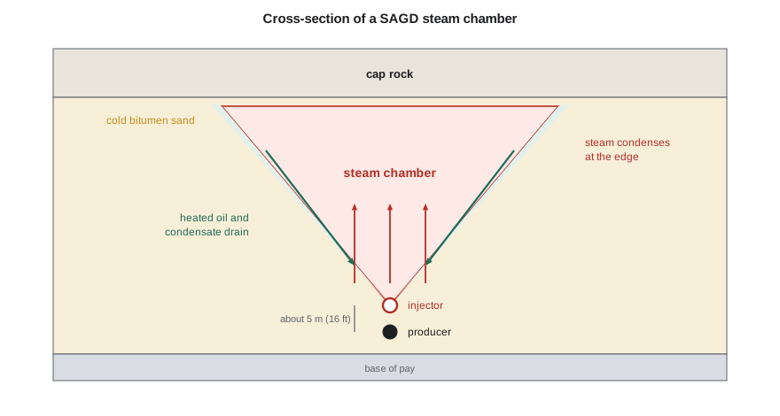
A SAGD well pair consists of two parallel horizontal wells drilled near the base of the pay. The producer is placed a few meters above the base of the oil, and the injector about 5 m (16 ft) above it. Horizontal lengths are typically 500 to 1,000 m (1,600 to 3,300 ft). Several pairs are drilled from one surface pad, usually 80 to 150 m (260 to 490 ft) apart, so that their chambers eventually merge. The wells are completed with slotted liners or wire-wrapped screens to keep the unconsolidated sand out, and often with two tubing strings that deliver steam or lift fluids at both the heel and the toe of the horizontal section.
The vertical spacing between injector and producer is a compromise. It must be large enough that steam does not short-circuit directly into the producer, and small enough that the bitumen between the wells can be heated and made mobile quickly at start-up. About 5 m (16 ft) has become the industry standard for Athabasca bitumen.
Start-up: establishing communication
Cold bitumen between the wells cannot flow, so a new well pair must first be heated until the two wells are connected by mobile fluid. The usual method is steam circulation: steam is circulated down the tubing and back up the annulus of both wells for typically two to four months, heating the surrounding sand by conduction until the bitumen between them flows. Operators then switch to SAGD mode, injecting into the upper well and producing from the lower one. Faster start-up methods are used too, including injecting at a pressure slightly above the reservoir pressure to dilate the sand, which increases its porosity and permeability, and adding solvents during circulation.
How the steam chamber grows
Once communication is established, steam injected into the upper well rises into the bitumen sand because it is less dense than the liquids around it. At the boundary of the steam-saturated zone, the steam chamber, steam meets cold sand and condenses, releasing its latent heat. That heat warms a thin layer of bitumen ahead of the chamber edge by conduction. The warmed bitumen, now with a viscosity of a few to a few tens of centipoise, drains by gravity along the sloping chamber wall, together with the condensed water, down to the producer. As the bitumen drains, steam fills the space it leaves, and the chamber expands upward and outward.
Chamber growth has two phases. In the rising phase, the chamber climbs toward the top of the pay, with high oil rates per unit of steam because heat losses to the overburden are still small. Once the chamber reaches the cap rock, it spreads sideways, and the sloping walls drain the bitumen between neighboring well pairs. Heat losses to the cap rock rise in this spreading phase because a growing area of hot rock is in contact with it, and the steam-oil ratio gradually increases. Eventually the chambers of neighboring pairs merge, and the oil rate declines as the remaining bitumen is drained from the wedges between them.
A key operating idea is that SAGD is a gravity process rather than a pressure-driven one. The pressure difference between injector and producer is kept small, and the producer is operated with a liquid pool above it so that steam does not flow straight into it. The temperature difference between the steam temperature and the produced fluid temperature, called the subcool, is the main control variable, as lesson 6 explains.
Butler's gravity drainage model
Butler modeled the drainage at the chamber edge by combining Darcy's law for flow along the inclined interface with a steady-state temperature profile ahead of it. Heat conducts ahead of the moving interface, the oil viscosity falls in that heated layer, and the oil drains under gravity. Integrating over the height of the chamber gave a simple and remarkably useful result for the oil drainage rate from both sides of a chamber per unit length of well:
Here L is the well length, k the effective permeability to oil, g the acceleration of gravity, α the thermal diffusivity of the reservoir, φ the porosity, ΔS_o the change in oil saturation from initial to residual, h the height of the chamber above the producer, ν_s the kinematic viscosity of the oil at steam temperature and m a dimensionless constant, typically 3 to 4, that describes how fast the viscosity rises with falling temperature away from the interface.
The equation says several useful things. The rate grows with the square root of permeability, thickness and porosity, and falls with the square root of the hot-oil viscosity. Doubling the pay thickness raises the rate per well pair by about 40 percent. Halving the permeability, or doubling the hot viscosity, lowers it by about 30 percent. Because of the square roots, SAGD is forgiving of moderate variations in these properties but very sensitive to anything that changes the effective height of the chamber, such as mud layers that stop it rising.
# Butler's gravity drainage estimate for one SAGD well pair
import math
SI = False
g = 9.81
def butler(L, k_darcy, phi, dSo, h, alpha, nu_s, m=3.5):
    k = k_darcy * 0.9869e-12                  # m2
    return 2 * L * math.sqrt(2 * k * g * alpha * phi * dSo * h / (m * nu_s))   # m3/s, both sides of the chamber
L, k, phi, dSo, alpha = 800.0, 3.0, 0.33, 0.60, 7.0e-7       # m, darcies, -, -, m2/s
nu_s = 1.0e-5                                              # m2/s: about 10 cP oil at density near 1,000 kg/m3 (steam temperature)
for h in (10.0, 20.0, 30.0):
    q = butler(L, k, phi, dSo, h, alpha, nu_s) * 86400
    if SI: print(f"pay thickness {h:4.0f} m  ->  rate {q:6.0f} m3/d per well pair")
    else:  print(f"pay thickness {h * 3.2808:4.0f} ft ->  rate {q * 6.2898:6.0f} bbl/d per well pair")
h = 25.0
q25 = butler(L, k, phi, dSo, h, alpha, nu_s) * 86400
for f, label in ((0.5, "half the permeability"), (2.0, "twice the oil viscosity at steam temperature")):
    kk = k * f if "perm" in label else k
    nn = nu_s * f if "visc" in label else nu_s
    q = butler(L, kk, phi, dSo, h, alpha, nn) * 86400
print(f"{label}: rate falls to {q / q25:.0%} of the base case")pay thickness 33 ft -> rate 1319 bbl/d per well pair pay thickness 66 ft -> rate 1865 bbl/d per well pair pay thickness 98 ft -> rate 2284 bbl/d per well pair half the permeability: rate falls to 71% of the base case twice the oil viscosity at steam temperature: rate falls to 71% of the base case
Ethan's calculation gives about 1,900 bbl/d for a 66 ft chamber, rising to about 2,300 bbl/d for 98 ft. Paul is not surprised. 'Butler's equation is an ideal,' he says. 'Real Alberta well pairs average about half that, because the effective permeability is lower than the clean-sand value, shale layers cut the chamber height and the chamber does not drain evenly along the whole well. But the equation is right about the trends, and that is how we use it: to rank targets and to see what matters.'
What makes a good SAGD target
Experience from Alberta's projects has produced a fairly consistent picture of a good SAGD reservoir. The continuous pay should be thick, generally more than about 15 to 20 m (50 to 65 ft), so that the chamber can rise high enough to give good rates and a low steam-oil ratio before heat losses dominate. The sand should have high vertical as well as horizontal permeability, with few laterally extensive mud layers. Bitumen saturation should be high, usually above about 0.6 to 0.7 in the pay. There should be no large active water zone directly beneath the wells and no gas or water thief zone above that could drain the chamber's heat or pressure. The cap rock must be continuous and strong enough for the planned operating pressure. Depth affects the economics in two ways: deeper reservoirs allow higher operating pressures but need longer wells and lose more heat in the wellbore.
Each of these factors shows up in the steam-oil ratio. Thin pay, mud layers and thief zones all raise the SOR, which raises fuel, water and carbon costs. That is why development teams map the reservoir in such detail before choosing where to put a pad.
From pilot to industry
Butler's idea was first tested in the field at the Underground Test Facility in Alberta in the late 1980s and 1990s, a research project in which wells were drilled from tunnels beneath the oil sands so they could be placed accurately before long horizontal wells from surface were routine. The pilot showed that steam chambers grew as predicted and that steam-oil ratios near 2.5 were achievable. Commercial projects followed from about 2001, and SAGD and related processes now produce most of Alberta's in situ bitumen, which reached a record of about two million barrels a day in late 2025. In the United States, SAGD has been tried only in a few pilots, because most American heavy oil is mobile enough when hot to be produced by steamflooding or cyclic steam.
Worked problem
Rate per well pair from Butler’s equation
A well pair is 2,460 ft (750 m) long in sand with k = 2.5 D (2.47 × 10⁻¹² m²), φ = 0.32, ΔS_o = 0.6, α = 7 × 10⁻⁷ m²/s and h = 59 ft (18 m). The oil at steam temperature has ν_s = 1.0 × 10⁻⁵ m²/s, and m = 3.5. Estimate the drainage rate.
Show solution
- Inside the square root: 2 × 2.47 × 10⁻¹² × 9.81 × 7 × 10⁻⁷ × 0.32 × 0.6 × 18 / (3.5 × 1.0 × 10⁻⁵) = 3.36 × 10⁻¹² m²/s².
- The square root is 1.83 × 10⁻⁶ m²/s.
- q = 2 × 750 × 1.83 × 10⁻⁶ = 2.75 × 10⁻³ m³/s, or about 238 m³/d.
Answer: About 240 m³/d (about 1,500 bbl/d) from Butler's ideal model. A realistic field estimate, allowing for heterogeneity and uneven chamber development, might be about half that.
Monitoring the chamber
Because the steam chamber cannot be seen directly, operators use several kinds of monitoring to track it. Temperature strings of thermocouples or fiber-optic cable in the wells and in nearby observation wells show where the chamber has reached and how hot it is. Repeated seismic surveys, called 4D seismic, show where steam has replaced bitumen, because hot, gas-filled sand transmits seismic waves differently from cold bitumen sand. Surface heave, measured with satellite radar or tiltmeters, shows where the reservoir has expanded. Pressure gauges and produced fluid temperatures complete the picture. Together these let engineers compare the chamber with Butler's ideal, find parts of a well that are not draining and adjust steam splits or plan infill wells. Chamber monitoring is also part of the containment case: regulators expect operators to show that steam is staying in the target zone.
Common mistakes
MistakeExpecting SAGD to work in thin pay.
InsteadThin pay keeps the chamber short and heat losses high; most projects need more than about 15 to 20 m (50 to 65 ft).
MistakeDriving SAGD with a large pressure difference.
InsteadSAGD is a gravity process; keep a small pressure difference and control subcool.
MistakeTaking Butler's rate as a forecast.
InsteadUse it to rank targets and trends; field rates are typically lower.
MistakeIgnoring vertical permeability.
InsteadMud layers and low vertical permeability stop chambers rising and raise the SOR.
Summary and key terms
- A SAGD well pair has a horizontal injector about 5 m (16 ft) above a horizontal producer near the base of the pay.
- Start-up usually circulates steam in both wells for a few months to establish communication.
- Steam condenses at the chamber edge; heated bitumen and condensate drain by gravity to the producer.
- Chambers rise to the cap rock, then spread sideways and merge; the SOR rises as heat losses grow.
- Butler's equation gives the drainage rate as proportional to the square root of k, φ, ΔS_o and h over hot viscosity.
- Good targets have thick continuous pay, high vertical permeability, high saturation, no thief zones and sound cap rock.
- SAGD
- Steam-assisted gravity drainage, using a horizontal injector above a horizontal producer.
- Steam chamber
- The steam-saturated zone that grows above a SAGD well pair.
- Steam circulation
- Start-up by circulating steam in both wells to heat the bitumen between them.
- Subcool
- The difference between steam temperature and produced fluid temperature at the producer.
- Butler equation
- An analytical model of gravity drainage rate along a steam chamber edge.
- Underground Test Facility
- An Alberta research pilot that first proved SAGD in the field using wells drilled from tunnels.
Practice problems
Work each problem on paper first, then reveal the answer to check.
Why is the injector placed above the producer?
Show answer
Steam rises into the sand and heated oil drains down by gravity to the producer.
How does the rate change if the pay thickness doubles?
Show answer
It rises by about the square root of two, about 40 percent.
Why does the SOR rise when chambers reach the cap rock?
Show answer
A growing area of hot rock loses heat to the cap rock.
What is the purpose of steam circulation?
Show answer
To heat the bitumen between the wells until they communicate.
Lesson quiz · 5 questions
Score 60% or more to complete this lesson.
Create a free account to save your progress, take quizzes and earn a certificate.