
NUC-499 · Lesson 5 of 12 · 26 min
Thermal hydraulic design
Mira's task is to show that 10 MWt can be carried from the fuel to the campus network without pumps in the core and without boiling anywhere on the fuel surface, as requirements R-05 and R-06 demand. She starts from the pool layout agreed at the concept gate: an open pool 6 m across with 11 m of water, the core at the bottom, a chimney above the core to strengthen the natural circulation, and a heat exchanger in the pool that transfers heat to an intermediate loop. Her first calculation fails the boiling requirement by almost 10 K. This lesson follows how she finds out why, what she changes, and how the changes ripple through the rest of the design.
This lesson develops the thermal hydraulic design of a natural circulation pool reactor: the momentum balance that sets the flow, the heat transfer from the fuel to the coolant, the hot channel and its margins to nucleate boiling and critical heat flux, the temperature profile inside a fuel rod, and the heat exchangers that connect the pool to the campus. It shows how a design iterates between thermal hydraulics, neutronics and the requirements.
The heat path
Heat generated in the fuel pellets is conducted through the pellet, across the small gap between pellet and cladding, and through the cladding to the water flowing upward between the rods. The heated water rises through the chimney, flows outward across the top of the pool, passes down through the pool heat exchanger where it gives up its heat to the intermediate loop, and returns, cooler and denser, to the bottom of the pool and the core inlet. The intermediate loop carries the heat out of the reactor building to a second heat exchanger, where it passes to the campus hot water network.
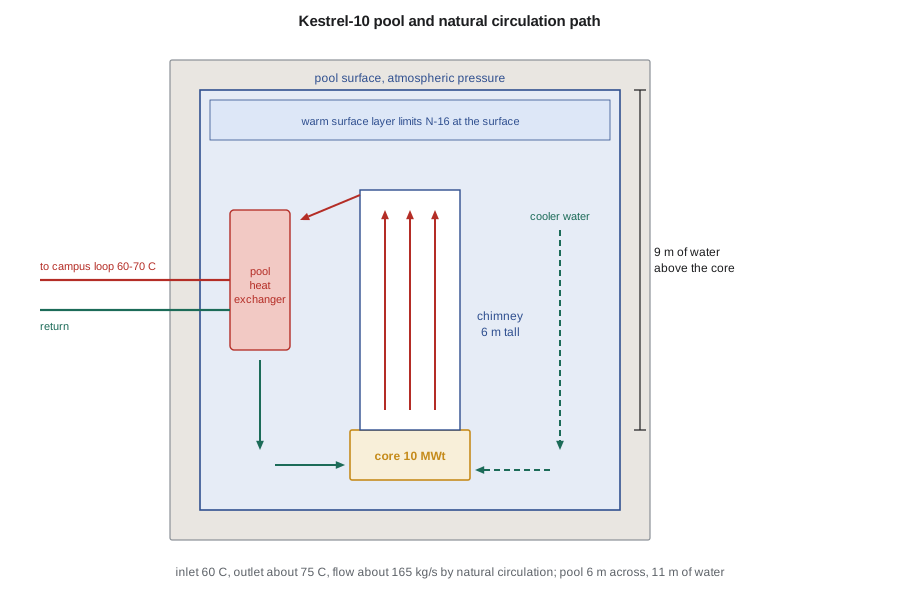
Every step of the path has a temperature difference, and those differences add up. The campus needs at least 65 °C(149 °F) supply water. Each heat exchanger needs a temperature difference of a few kelvin between its hot and cold sides to transfer heat at a practical size. So the pool water entering the heat exchanger must be several kelvin hotter than the intermediate loop, which must be several kelvin hotter than the campus supply. At the other end, the core outlet temperature is limited by the need to keep the fuel surface well below boiling. The thermal hydraulic design lives in the narrow window between these constraints.
Natural circulation
In natural circulation, the driving force is the weight difference between the cold leg, where the water descends past the heat exchanger, and the hot leg, where it rises through the core and chimney. For a loop with a heated core and an unheated chimney above it, the driving pressure is approximately
The flow settles where this driving pressure equals the losses in the loop: friction along the rods, and form losses at the core inlet, the spacer grids, the core outlet and the chimney exit. Both sides depend on the flow. A higher flow increases the losses with the square of the velocity, and it also reduces the temperature rise across the core and therefore the density difference that drives the flow. The two effects combine to make natural circulation self-regulating: if the power rises, the water heats more, the driving force increases and the flow rises to carry the extra heat. The solution is found by iteration, starting from a guessed flow and updating it until the driving pressure and the losses balance.
The chimney is what makes natural circulation work at this power. Without it, the driving head would come only from the heated length of about 1.2 m, and the flow would be too small to keep the core outlet temperature down. A chimney several meters tall multiplies the driving head several times over at little cost, provided the hot water inside it stays separate from the cooler water around it. The same principle is used in boiling water reactors with natural circulation and in many research and heating reactor designs.
# Natural circulation through the Kestrel-10 core and chimney, hot-channel temperatures and boiling margins.
import math
P, cp, g = 10.0e6, 4190.0, 9.81
A_flow, D_h, H_core = 25 * 0.0245, 0.0118, 1.20       # m^2, m, m
N_rods, d_o = 25 * 264, 0.0095
K_loss = 9.0                                          # inlet, grids, outlet and chimney form losses
def rho(T): return 1000.6 - 0.0128 * T - 0.00355 * T * T          # kg/m^3, liquid water near 1 to 2 bar
def mu(T): return 2.414e-5 * 10 ** (247.8 / (T + 133.15))          # Pa s
def t_sat(p_bar): return 100.0 + 29.7 * math.log(p_bar / 1.013)    # C, fit for 1 to 2.5 bar
def q_onb(dT, p_bar): return 1082 * p_bar ** 1.156 * (1.8 * dT) ** (2.16 / p_bar ** 0.0234)   # Bergles-Rohsenow, W/m^2
def dT_onb(q, p_bar):          # invert Bergles-Rohsenow by bisection
    lo, hi = 0.01, 60.0
    for _ in range(60):
        mid = 0.5 * (lo + hi)
        lo, hi = (mid, hi) if q_onb(mid, p_bar) < q else (lo, mid)
    return mid
def design(T_in, H_chim, F_q, depth):
    m = 50.0
    for _ in range(300):       # buoyancy head = friction + form losses
        T_out = T_in + P / (m * cp); Tm = 0.5 * (T_in + T_out)
        drive = g * (rho(T_in) - rho(T_out)) * (H_chim + H_core / 2)
        v = m / (rho(Tm) * A_flow); Re = rho(Tm) * v * D_h / mu(Tm)
        K = K_loss + 0.316 * Re ** -0.25 * H_core / D_h
        m_new = rho(Tm) * A_flow * math.sqrt(2 * drive / (rho(Tm) * K))
        if abs(m_new - m) < 1e-5: break
        m = 0.5 * (m + m_new)
    q_pk = F_q * P / (N_rods * H_core) / (math.pi * d_o)               # peak heat flux, W/m^2
    h = 0.023 * Re ** 0.8 * 2.4 ** 0.4 * 0.665 / D_h                    # Dittus-Boelter
    T_bulk = T_in + 0.8 * min(1.6, F_q / 1.45) * (T_out - T_in)        # hot-channel bulk at the peak-flux elevation
    T_wall = T_bulk + q_pk / h
    p_bar = 1.013 + rho(Tm) * g * depth / 1e5
    Ts = t_sat(p_bar)
    limit = Ts + dT_onb(q_pk, p_bar)
    print(f"  flow {m:.0f} kg/s, velocity {v:.3f} m/s, outlet {T_out:.1f} C (rise {T_out - T_in:.1f} K)")
    print(f"  peak heat flux {q_pk / 1000:.0f} kW/m^2, h = {h:,.0f} W/m^2K, hot-spot wall {T_wall:.1f} C")
    print(f"  saturation {Ts:.1f} C at {p_bar:.2f} bar; onset of nucleate boiling at {limit:.1f} C; ONB margin {limit - T_wall:+.1f} K")
    return q_pk, p_bar
print("Initial design: inlet 70 C, 4 m chimney, F_q = 2.3, hot spot 7.4 m below the surface")
design(70.0, 4.0, 2.3, 7.4)
print("Revised design: inlet 60 C, 6 m chimney, F_q = 1.9, hot spot 9.4 m below the surface")
q_pk, p_bar = design(60.0, 6.0, 1.9, 9.4)
rho_g, h_fg, sigma = 1.05, 2.21e6, 0.055                              # pool-boiling CHF (Zuber), conservative for low flow
q_chf = 0.131 * h_fg * rho_g ** 0.5 * (sigma * g * (rho(t_sat(p_bar)) - rho_g)) ** 0.25
print(f"Zuber critical heat flux {q_chf / 1e6:.2f} MW/m^2; minimum CHF ratio {q_chf / q_pk:.1f}")Initial design: inlet 70 C, 4 m chimney, F_q = 2.3, hot spot 7.4 m below the surface flow 153 kg/s, velocity 0.256 m/s, outlet 85.6 C (rise 15.6 K) peak heat flux 97 kW/m^2, h = 2,484 W/m^2K, hot-spot wall 128.9 C saturation 115.8 C at 1.72 bar; onset of nucleate boiling at 119.2 C; ONB margin -9.7 K Revised design: inlet 60 C, 6 m chimney, F_q = 1.9, hot spot 9.4 m below the surface flow 165 kg/s, velocity 0.274 m/s, outlet 74.5 C (rise 14.5 K) peak heat flux 80 kW/m^2, h = 2,350 W/m^2K, hot-spot wall 109.4 C saturation 119.0 C at 1.92 bar; onset of nucleate boiling at 121.9 C; ONB margin +12.6 K Zuber critical heat flux 1.41 MW/m^2; minimum CHF ratio 17.6
The hot channel and boiling margins
The average conditions in the core are not what limit the design; the hot spot is. The hot channel is the coolant channel next to the rod with the highest linear heat rate, at the elevation where that heat rate peaks. Its wall temperature is the bulk coolant temperature at that point plus the temperature difference across the boundary layer, which equals the local heat flux divided by the heat transfer coefficient. For turbulent flow along a rod bundle, the Dittus-Boelter correlation gives a reasonable estimate of the coefficient for a concept study:
Nucleate boiling begins when the wall is hot enough above the local saturation temperature for vapor bubbles to form and grow at small cavities in the surface. The wall superheat needed depends on the heat flux and the pressure; the Bergles-Rohsenow correlation gives the heat flux at which boiling starts for a given superheat, and inverting it gives the wall temperature at which boiling would begin for the actual heat flux. The saturation temperature itself depends on the depth of water above the hot spot, because the pool surface is at atmospheric pressure and the pressure at depth adds the weight of the water above it. At about 9 m below the surface, the pressure is close to 2 bar and the saturation temperature close to 119 °C(246 °F).
Mira's initial design had a core inlet of 70 °C, a 4 m chimney and a total peaking factor of 2.3. The calculation shows a natural circulation flow of about 153 kg/s, a core outlet of about 86 °C, a peak heat flux of 97 kW/m² and a hot-spot wall temperature of about 129 °C, nearly 10 K above the temperature at which nucleate boiling would begin. The design fails R-05. Local subcooled boiling at the hot spot would not damage the fuel, since the heat flux is more than an order of magnitude below the critical heat flux, but it would complicate the core behavior, introduce small void reactivity effects and make the design harder to analyze and license. The team's requirement exists precisely to avoid those complications.
Iterating the design
The calculation shows which parameters matter. The wall superheat depends on the heat flux, so lowering the peaking factor helps directly. The bulk temperature depends on the inlet temperature and the flow, so lowering the inlet temperature and raising the flow both help. And the boiling limit rises with pressure, so placing the core deeper in the pool raises the saturation temperature. Mira discusses each option with the area it affects. Kofi agrees that a peaking factor of 1.9 is achievable by redistributing the gadolinia and adjusting the rod pattern. The civil designers consulted by Nikolai confirm that the pool could be 2 m deeper, which also adds shielding. A 6 m chimney instead of 4 m increases the driving head. And Hana checks the inlet temperature change against R-01.
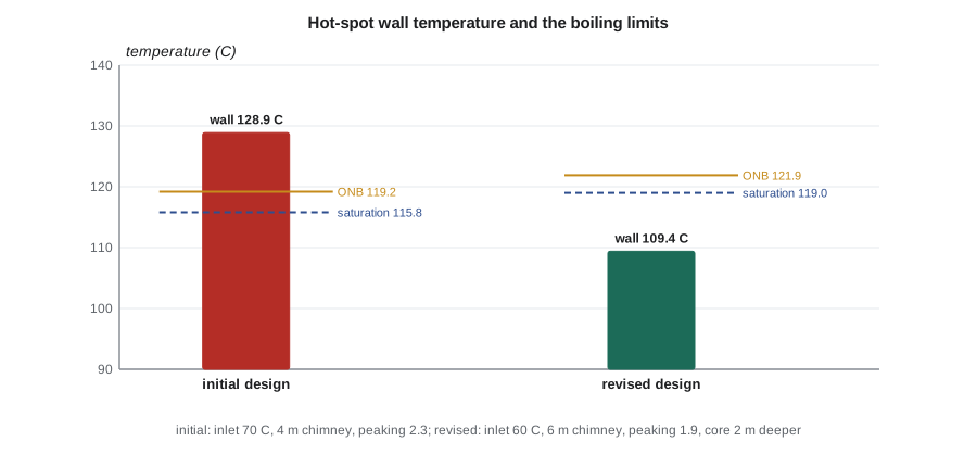
The revised design has a core inlet of 60 °C(140 °F), a 6 m chimney, a peaking factor of 1.9 and the hot spot 9.4 m below the surface. The flow rises to about 165 kg/s, the core outlet is about 75 °C(167 °F), the peak heat flux falls to 80 kW/m², and the hot-spot wall is at about 109 °C, more than 12 K below the boiling limit. R-05 is met. The critical heat flux, estimated conservatively with the Zuber pool-boiling correlation because the flow velocity is low, is about 1.4 MW/m², giving a minimum critical heat flux ratio of about 18. Power reactors operate with minimum ratios of about 1.3 to 2; the Kestrel-10 margin reflects its very low power density.
The cost of the change appears elsewhere. With a core outlet of about 75 °C, the pool water reaching the heat exchanger is about 74 °C, the intermediate loop leaves the pool heat exchanger at about 70 °C, and the campus supply reaches about 66 °C. R-01 is still met, but only just, and on the coldest days the gas boilers will need to boost the supply temperature. Hana records the reduced margin on R-01 as a risk and asks Mira to check whether the heat exchangers can be made larger to gain a degree or two.
Temperatures inside the fuel rod
At the hot spot, heat flows outward through the pellet, the gas gap and the cladding. For a solid cylindrical pellet with uniform heat generation and constant conductivity, the temperature rise from the surface to the centerline depends only on the linear heat rate, not on the pellet radius:
# Radial temperature profile at the hot spot of the revised design: coolant to fuel centerline.
import math
q_lin = 2.40e3                 # W/m, peak linear power (F_q = 1.9 times the 1.26 kW/m average)
T_wall = 109.4                 # C, hot-spot cladding surface from the natural circulation calculation
r_o, r_i, r_f = 4.75e-3, 4.18e-3, 4.10e-3      # cladding outer and inner radius, pellet radius (m)
k_clad, h_gap, k_fuel = 17.0, 5000.0, 3.6      # W/mK, W/m^2K, W/mK (UO2 near 200 C)
dT_clad = q_lin * math.log(r_o / r_i) / (2 * math.pi * k_clad)
dT_gap = q_lin / (2 * math.pi * r_f * h_gap)
dT_fuel = q_lin / (4 * math.pi * k_fuel)
T_ci = T_wall + dT_clad; T_fs = T_ci + dT_gap; T_cl = T_fs + dT_fuel
for name, T in (("cladding outer surface", T_wall), ("cladding inner surface", T_ci), ("pellet surface", T_fs), ("fuel centerline", T_cl)):
    print(f"{name:24s}{T:7.1f} C")
print(f"volume-average fuel temperature about {T_fs + dT_fuel / 2:.0f} C; UO2 melts near 2,840 C")
# Compare with a typical power reactor rod at 18 kW/m
for q in (2.4e3, 18e3):
print(f"linear power {q / 1000:5.1f} kW/m -> pellet temperature rise {q / (4 * math.pi * k_fuel):6.0f} K")cladding outer surface 109.4 C cladding inner surface 112.3 C pellet surface 130.9 C fuel centerline 184.0 C volume-average fuel temperature about 157 C; UO2 melts near 2,840 C linear power 2.4 kW/m -> pellet temperature rise 53 K linear power 18.0 kW/m -> pellet temperature rise 398 K
The fuel centerline at the hot spot reaches only about 184 °C(363 °F). A power reactor rod at 18 kW/m would see a temperature rise across the pellet of about 400 K at this conductivity, and in practice more, because uranium oxide conducts heat less well at high temperature; its centerline might be well over 1,000 °C. The low fuel temperatures of Kestrel-10 have several consequences. Fission gas release from the pellets is negligible, so the fuel rods do not pressurize over their life. The Doppler feedback is small in absolute terms, because the fuel temperature changes little with power. And the stored heat in the fuel is small, so in an accident there is little heat to remove beyond decay heat.
Heat exchangers and the intermediate loop
The pool heat exchanger must transfer 10 MW with a small temperature difference, which makes it large. The required product of the overall heat transfer coefficient U and area A follows from the log mean temperature difference across the exchanger:
Mira chooses plate heat exchangers for both stages, because they achieve high coefficients at small temperature differences and can be cleaned and inspected easily. The pool heat exchanger sits in the pool, on the downcomer side, so that the water it cools sinks naturally back toward the core inlet. The intermediate loop is pumped, since it is outside the core and its failure does not affect fuel cooling directly: if the intermediate loop stops, the pool simply heats up slowly while the decay heat is absorbed, as the safety analysis will show. A small purification circuit draws water from the pool through filters and ion exchange beds to keep the water clean and its conductivity low, which protects the cladding and limits the activity of corrosion products.
Two further features complete the thermal hydraulic design. A warm surface layer, a few kelvin hotter than the water below, is maintained by a small separate flow, so that the cooler water rising from the chimney cannot reach the surface. This keeps short-lived activation products, especially nitrogen-16, away from the pool surface, as the shielding lesson will show. And the pool is sized so that it can absorb decay heat for many days with no heat exchanger operating, which is the basis of the passive safety case.
Worked problem
Sizing the pool heat exchanger
The pool water enters the pool heat exchanger at 74.5 °C and leaves at 60 °C. The intermediate loop enters at 55 °C and leaves at 70 °C, in counterflow. With an overall coefficient of 2,500 W/m²K, what area is needed for 10 MW?
Show solution
- Hot end difference = 74.5 − 70 = 4.5 K; cold end difference = 60 − 55 = 5.0 K.
- Log mean temperature difference = (5.0 − 4.5) ÷ ln(5.0 ÷ 4.5) = 0.5 ÷ 0.1054 = 4.75 K.
- UA = 10 × 10⁶ ÷ 4.75 = 2.11 × 10⁶ W/K.
- A = 2.11 × 10⁶ ÷ 2,500 = 842 m².
Answer: About 840 m², which plate heat exchangers can provide in a compact unit. The small temperature differences are the price of delivering useful campus temperatures from a low-temperature reactor.
Common mistakes
MistakeNatural circulation flow is fixed by the pool size.
InsteadIt is set by the balance of buoyancy head and loop losses, and it rises with power.
MistakeThe average channel limits the design.
InsteadThe hot channel at the peak heat flux elevation sets the boiling margin.
MistakeThe saturation temperature in an open pool is 100 °C everywhere.
InsteadIt rises with depth; at 9 m it is close to 119 °C.
MistakeLowering the core inlet temperature has no downside.
InsteadIt lowers the supply temperature available to the campus, reducing margin on R-01.
Summary and key terms
- Heat flows from pellet to coolant, up the chimney, through the pool heat exchanger and the intermediate loop to the campus.
- Natural circulation flow balances buoyancy head against friction and form losses; a chimney multiplies the head.
- The hot-spot wall temperature is compared with the onset of nucleate boiling at the local pressure.
- The initial design failed R-05; a lower inlet temperature, a taller chimney, lower peaking and a deeper core gave more than 12 K of margin.
- The fuel centerline is below 200 °C, giving negligible fission gas release and little stored heat.
- Large plate heat exchangers deliver about 66 °C to the campus, meeting R-01 with a small margin.
- Natural circulation
- Flow driven by density differences between hot and cold parts of a loop.
- Chimney
- A tall riser above the core that increases the buoyancy head.
- Hot channel
- The coolant channel next to the highest-power rod, where margins are smallest.
- Onset of nucleate boiling
- The condition at which bubbles begin to form on a heated surface.
- Critical heat flux
- The heat flux at which boiling becomes unstable and the surface temperature rises sharply.
- Log mean temperature difference
- The effective temperature difference driving heat transfer in a heat exchanger.
- Intermediate loop
- A closed loop between the reactor pool and the user that isolates the user from primary water.
Practice problems
Work each problem on paper first, then reveal the answer to check.
Why does natural circulation flow increase when power increases?
Show answer
The hot leg becomes less dense, so the driving head rises and the flow increases until losses balance it.
Why is the saturation temperature at the hot spot above 100 °C?
Show answer
The hot spot is about 9 m below the surface, where the pressure is close to 2 bar.
Name three changes that gave the revised design its boiling margin.
Show answer
A lower inlet temperature, a taller chimney, a lower peaking factor and a deeper core (any three).
Why is the fuel centerline temperature so low?
Show answer
The peak linear heat rate is only about 2.4 kW/m.
Why are the heat exchangers large?
Show answer
They must transfer 10 MW across temperature differences of only a few kelvin.
Lesson quiz · 5 questions
Score 60% or more to complete this lesson.
Create a free account to save your progress, take quizzes and earn a certificate.