
MEC-450 · Lesson 10 of 12 · 23 min
Heat transfer by finite elements
The mining customer runs some of its pumps on hot process water at up to 120 °C. In the standard TP-80, heat flows from the casing through a cast adapter into the bearing frame, and the bearing temperature is kept below its limit by the frame's surface losses. For the heavier-duty version, Farah wants to know how hot the adapter's far end gets, how much heat reaches the bearing frame, and whether the temperature difference across the casing produces thermal stress worth worrying about. All three questions are answered by finite element heat transfer analysis, which uses exactly the machinery of the previous lessons with temperature as the unknown. This lesson develops it, tests it against two exact solutions and shows how thermal results feed a stress model.
The conduction equation and its weak form
Steady heat conduction in a solid obeys Fourier's law, \(q = -k\nabla T\), and conservation of energy, which together give \(\nabla\cdot(k\nabla T) + Q = 0\), where Q is any internal heat generation. Boundaries can have a prescribed temperature, a prescribed heat flux or a convection condition \(q = h(T - T_\infty)\) to a surrounding fluid. Galerkin's method from Lesson 5 gives a weak form in which only first derivatives of T appear, and the shape functions of Lessons 2, 6 and 7 apply unchanged. The element matrix, now called the conductance matrix, is
where B now holds the temperature gradients of the shape functions and k is the thermal conductivity. The second term, from convection, makes the matrix depend on the film coefficient h as well as the conductivity, and the load vector gains a matching term \(\int hT_\infty N^{\mathsf{T}}\,dS\). Each node has one degree of freedom, its temperature, so thermal models are a third the size of structural models with the same mesh.
The adapter as a fin
The adapter is a cast ring joining the casing to the bearing frame, and heat flows along it while leaking from its outer surface to the surrounding air. One-dimensionally, it behaves like a fin, a problem with a well-known exact solution. Owen represents it by an equivalent steel bar 0.12 m long with conductivity 45 W/m·K, cross-sectional area 1.2 × 10⁻³ m² and a wetted perimeter of 0.40 m, with the base held at the 120 °C casing temperature and air at 25 °C on the sides and the end, with a film coefficient of 12 W/m²·K, a typical value for still air with some radiation. The fin parameter is \(m = \sqrt{hP/kA} = 9.43\) m⁻¹, so mL = 1.13, and the exact solution, including convection from the end face, gives an end temperature of 79.27 °C and a heat flow into the adapter of 39.71 W.
The finite element model uses two-node elements along the bar. Each has the conduction matrix of a bar, \((kA/l)\begin{bmatrix} 1 & -1 \\ -1 & 1\end{bmatrix}\), plus the side-convection matrix \((hPl/6)\begin{bmatrix} 2 & 1 \\ 1 & 2\end{bmatrix}\). The end face adds hA to the last diagonal term. The base temperature is prescribed, like a support, and the heat flow into the adapter is recovered from the base node's row, exactly as a reaction force was recovered in Lesson 1.
# Heat transfer by finite elements: the casing-to-bearing-frame adapter as a fin, and 2D conduction in a square
import math
def solve(A, b):
    n = len(b); A = [r[:] for r in A]; b = b[:]
    for k in range(n):
        p = max(range(k, n), key=lambda i: abs(A[i][k])); A[k], A[p] = A[p], A[k]; b[k], b[p] = b[p], b[k]
        for i in range(k + 1, n):
            f = A[i][k] / A[k][k]
            if f:
                for j in range(k, n): A[i][j] -= f * A[k][j]
                b[i] -= f * b[k]
    x = [0.0] * n
    for i in range(n - 1, -1, -1): x[i] = (b[i] - sum(A[i][j] * x[j] for j in range(i + 1, n))) / A[i][i]
    return x
# Adapter: equivalent steel bar k 45 W/m K, area 1.2e-3 m^2, wetted perimeter 0.40 m, length 0.12 m,
# base at the 120 C casing, air at 25 C with h = 12 W/m^2 K on the sides and the end
k, Ac, Pm, L, h, Tb, Ta = 45.0, 1.2e-3, 0.40, 0.12, 12.0, 120.0, 25.0
m = math.sqrt(h * Pm / (k * Ac))
def exact(x):
    return Ta + (Tb - Ta) * (math.cosh(m*(L-x)) + h/(m*k) * math.sinh(m*(L-x))) / (math.cosh(m*L) + h/(m*k) * math.sinh(m*L))
q_exact = k * Ac * m * (Tb - Ta) * (math.sinh(m*L) + h/(m*k) * math.cosh(m*L)) / (math.cosh(m*L) + h/(m*k) * math.sinh(m*L))
def fin(ne):
    n = ne + 1; le = L / ne; K = [[0.0] * n for _ in range(n)]; F = [0.0] * n
    for e in range(ne):
        kc, kh = k * Ac / le, h * Pm * le / 6      # conduction and side-convection element matrices
        for a, b, v in ((e, e, kc + 2*kh), (e+1, e+1, kc + 2*kh), (e, e+1, -kc + kh), (e+1, e, -kc + kh)): K[a][b] += v
        F[e] += h * Pm * le / 2 * Ta; F[e+1] += h * Pm * le / 2 * Ta
    K[-1][-1] += h * Ac; F[-1] += h * Ac * Ta       # convection from the end face
    rhs = [F[i] - K[i][0] * Tb for i in range(1, n)]
    T = [Tb] + solve([r[1:] for r in K[1:]], rhs)
    q = sum(K[0][j] * T[j] for j in range(n)) - F[0]   # heat entering at the base = reaction at the fixed node
    return T, q
print(f"m = {m:.2f} 1/m, mL = {m*L:.3f}; exact end temperature {exact(L):.2f} C, heat flow {q_exact:.2f} W")
for ne in (1, 2, 4, 8):
    T, q = fin(ne)
    print(f"  {ne} elements: end temperature {T[-1]:7.2f} C, heat into the adapter {q:6.2f} W ({100*(q-q_exact)/q_exact:+.2f} %)")

# 2D steady conduction in a square plate: one edge held at 100 C, the other three at 0 C.
# By symmetry and superposition the exact center temperature is 25 C. Linear triangles on an n x n grid.
def square(n):
    hgrid = 1.0 / n; nid = lambda i, j: j * (n + 1) + i; N = (n + 1)**2
    K = [[0.0] * N for _ in range(N)]
    for j in range(n):
        for i in range(n):
            for tri in ((nid(i, j), nid(i+1, j), nid(i+1, j+1)), (nid(i, j), nid(i+1, j+1), nid(i, j+1))):
                xy = [((t % (n+1)) * hgrid, (t // (n+1)) * hgrid) for t in tri]
                (x1, y1), (x2, y2), (x3, y3) = xy
                A2 = (x2-x1)*(y3-y1) - (x3-x1)*(y2-y1); b = [y2-y3, y3-y1, y1-y2]; c = [x3-x2, x1-x3, x2-x1]
                for p in range(3):
                    for q in range(3): K[tri[p]][tri[q]] += (b[p]*b[q] + c[p]*c[q]) / (2 * A2)
    Tfix = {}
    for i in range(n + 1):
        Tfix[nid(i, 0)] = 0.0; Tfix[nid(0, i)] = 0.0; Tfix[nid(n, i)] = 0.0
    for i in range(1, n): Tfix[nid(i, n)] = 100.0
    free = [a for a in range(N) if a not in Tfix]
    rhs = [-sum(K[a][b] * v for b, v in Tfix.items()) for a in free]
    T = dict(Tfix); T.update(zip(free, solve([[K[a][b] for b in free] for a in free], rhs)))
    return T[nid(n // 2, n // 2)], T[nid(n // 2, 3 * n // 4)]
ex = sum(400 / (j * math.pi) * math.sinh(j * math.pi * 0.75) / math.sinh(j * math.pi) * math.sin(j * math.pi * 0.5) for j in range(1, 80, 2))
print(f"Exact series at (0.5, 0.75): {ex:.3f} C")
for n in (4, 8, 16):
    c, q = square(n)
print(f"Square, {n:2d} x {n:<2d} grid ({2*n*n:3d} triangles): center {c:6.3f} C, point (0.5, 0.75) {q:6.3f} C, error {q-ex:+.3f} C")m = 9.43 1/m, mL = 1.131; exact end temperature 79.27 C, heat flow 39.71 W 1 elements: end temperature 76.23 C, heat into the adapter 42.85 W (+7.93 %) 2 elements: end temperature 78.59 C, heat into the adapter 40.47 W (+1.93 %) 4 elements: end temperature 79.10 C, heat into the adapter 39.90 W (+0.48 %) 8 elements: end temperature 79.23 C, heat into the adapter 39.75 W (+0.12 %) Exact series at (0.5, 0.75): 54.053 C Square, 4 x 4 grid ( 32 triangles): center 25.000 C, point (0.5, 0.75) 52.679 C, error -1.374 C Square, 8 x 8 grid (128 triangles): center 25.000 C, point (0.5, 0.75) 53.608 C, error -0.445 C Square, 16 x 16 grid (512 triangles): center 25.000 C, point (0.5, 0.75) 53.933 C, error -0.120 C
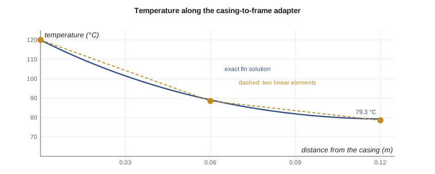
One element gives an end temperature 3 °C low and a heat flow 7.9 percent high; two elements reduce the heat flow error to 1.9 percent, and eight to 0.12 percent. The heat flow error falls by a factor of four each time the elements are halved, the h² behavior of a quantity that, like strain energy, is an integral over the whole model. The bearing frame receives about 40 W through the adapter, a small fraction of the pump's losses, so Owen concludes that the adapter will not overheat the bearings. A full three-dimensional thermal model of the frame would refine this, but the one-dimensional model has already answered the design question to within a few percent.
Two-dimensional conduction
The program's second model is a classic test: a square plate with one edge held at 100 °C and the other three at 0 °C. By symmetry and superposition, adding the four rotated versions of the problem gives a plate with all edges at 100 °C, which is 100 °C everywhere, so the center of the original plate must be exactly 25 °C. The exact temperature anywhere else is a Fourier series, and at the point halfway across and three quarters of the way toward the hot edge it is 54.05 °C.
The program meshes the square with linear triangles. The center temperature comes out as exactly 25 °C on every mesh, because the triangle mesh used here reproduces the discrete symmetry of the problem, a useful sanity check but not a proof of accuracy. At the off-center point the error falls from 1.37 °C on the 4 × 4 grid to 0.45 and 0.12 °C as the grid is halved, approaching the factor of four expected for linear elements. A test with a symmetry-guaranteed answer and one without is a good pair: the first catches assembly and boundary condition errors, the second measures accuracy.
Transient heat transfer
When the pump starts on hot water, the casing heats up over several minutes, and the stresses during that transient can exceed the steady-state ones, because the inside of the casing is hot while the outside is still cold. Transient analysis adds a capacitance matrix, \(C = \int \rho c\,N^{\mathsf{T}}N\,dV\), analogous to the mass matrix of Lesson 11, giving \(C\dot{T} + KT = F\). This is solved by stepping in time. The common family of methods, the θ-method, includes the explicit forward Euler scheme (θ = 0), the Crank-Nicolson scheme (θ = 1/2) and the implicit backward Euler scheme (θ = 1). Explicit schemes are simple but become unstable if the time step exceeds a limit proportional to the square of the smallest element size; implicit schemes are unconditionally stable but need a matrix solve each step, and Crank-Nicolson can produce oscillations near sudden changes. For a casing warm-up, backward Euler with time steps of a few seconds is a robust choice.
The time scale of a transient can be estimated by hand before modeling. The thermal diffusivity of steel is about \(1.2 \times 10^{-5}\) m²/s, so a 20 mm casing wall reaches near-uniform temperature in a time of the order of \(L^2/\alpha = 0.02^2/1.2 \times 10^{-5} \approx 33\) s after its inner surface is heated, and the whole casing, much of whose heating depends on surface convection, takes several minutes. A transient model whose results disagree with such an estimate by an order of magnitude needs to be checked.
From temperature to thermal stress
Thermal stress analysis uses the temperature field as a load. The usual workflow is sequential: run the thermal model, then map its nodal temperatures onto a structural model, often the same mesh, and apply them as initial strains \(\alpha(T - T_{ref})\), as Lesson 2 did for a single bar. Farah asks Owen to check the steady-state stress from the casing's through-wall temperature difference. A useful hand estimate for a plate whose faces differ by ΔT and whose edges cannot rotate is \(\sigma = E\alpha\Delta T/(2(1 - \nu))\). For the casing wall, with water at 120 °C inside and a film-limited outer surface, the thermal model shows a through-wall difference of about 4 °C, giving \(200\,000 \times 12 \times 10^{-6} \times 4/1.4 \approx 7\) MPa. That is small, so steady thermal stress is not a concern; the start-up transient, when the difference briefly reaches tens of degrees, is the case that needs checking against the casting's fatigue strength.
Worked problem
Heat into the bearing frame at a higher water temperature
The customer later asks about water at 150 °C. Using the linear model, estimate the adapter's heat flow and end temperature without rerunning it.
Show solution
- The problem is linear in the temperature excess above ambient.
- The excess at the base rises from 120 − 25 = 95 K to 150 − 25 = 125 K, a factor of 1.316.
- Heat flow 39.71 × 1.316 = 52.3 W.
- End temperature 25 + (79.27 − 25) × 1.316 = 96.4 °C.
Answer: About 52 W and 96 °C, as long as the film coefficient and conductivity are unchanged. Radiation, which grows with the fourth power of absolute temperature, makes the real problem slightly nonlinear.
Getting thermal boundary conditions right
Thermal models are only as good as their film coefficients, which depend on fluid velocity, geometry and orientation and are rarely known better than to within 20 to 50 percent. Correlations from heat transfer texts, which Owen used in his heat transfer course, are the usual source. Because the uncertainty is large, a thermal analysis should report the sensitivity of its key results to h, for example by running the model at the expected value and at half and double. For the adapter, the heat flow changes by much less than the film coefficient does, because the conduction resistance of the adapter also limits it, which is reassuring. Radiation is often included as an increment to h near the surface temperature, or modeled exactly as a nonlinear boundary condition.
Common mistakes
MistakePrescribing a temperature where the physics gives a convection condition.
InsteadUse convection with a film coefficient and fluid temperature where heat leaves to a fluid.
MistakeTreating film coefficients as precise.
InsteadReport sensitivity of key results to h, since it is usually uncertain by tens of percent.
MistakeRunning only the steady state when the start-up governs.
InsteadCheck transient through-wall differences, which can far exceed steady ones.
MistakeUsing an explicit time step larger than the stability limit.
InsteadUse an implicit scheme, or keep the explicit step below the limit set by the smallest element.
MistakeApplying temperatures to a structural model with the wrong reference temperature.
InsteadThermal strain is α(T − T_ref); use the stress-free assembly temperature.
Summary and key terms
- Steady conduction uses the same elements, with temperature as the single nodal unknown; convection adds terms to the matrix and load.
- The adapter fin model gives an end temperature of 79.27 °C and 39.71 W exactly; two elements are within 1.9 percent on heat flow.
- Heat flow error falls about fourfold per halving of element size.
- In the square plate test, the center is 25 °C on every mesh and the off-center error falls from 1.37 to 0.12 °C.
- Transient analysis adds a capacitance matrix and time stepping; implicit schemes are unconditionally stable.
- Thermal stress is computed by applying the temperature field as initial strain; start-up transients often govern.
- Thermal conductivity
- The material property k relating heat flux to temperature gradient.
- Conductance matrix
- The thermal counterpart of the stiffness matrix.
- Film coefficient
- The convection coefficient h relating surface heat flux to the surface-to-fluid temperature difference.
- Fin
- A conducting member that loses heat along its surface to a surrounding fluid.
- Fin parameter
- m = √(hP/kA), which sets how quickly a fin's temperature decays.
- Capacitance matrix
- The matrix ∫ρcNᵀN dV that stores heat in a transient analysis.
- θ-method
- A family of time-stepping schemes from explicit (θ = 0) to implicit (θ = 1).
- Thermal diffusivity
- α = k/(ρc), which sets the speed of transient conduction.
- Sequential thermal-stress analysis
- Solving for temperature first and applying it as a load in a structural model.
- Reference temperature
- The temperature at which the structure is free of thermal stress.
Practice problems
Work each problem on paper first, then reveal the answer to check.
A bar element 0.05 m long, k = 50 W/m·K, A = 1 × 10⁻³ m², has what conduction matrix?
Show answer
(50 × 0.001/0.05)\(\begin{bmatrix} 1 & -1 \\ -1 & 1 \end{bmatrix}\) = 1.0\(\begin{bmatrix} 1 & -1 \\ -1 & 1 \end{bmatrix}\) W/K.
From the program, what is the heat flow error with four elements?
Show answer
+0.48 percent (39.90 W against 39.71 W).
Why is the center of the square exactly 25 °C?
Show answer
Superposing the four rotated problems gives a uniform 100 °C, so each contributes a quarter at the center.
A wall of steel 40 mm thick: roughly how long for a surface temperature change to reach through it?
Show answer
L²/α = 0.04²/1.2 × 10⁻⁵ ≈ 130 s.
A plate's faces differ by 10 K with edges unable to rotate. Estimate the thermal stress for steel.
Show answer
200 000 × 12 × 10⁻⁶ × 10/1.4 ≈ 17 MPa.
Lesson quiz · 5 questions
Score 60% or more to complete this lesson.
Create a free account to save your progress, take quizzes and earn a certificate.