
MEC-450 · Lesson 11 of 12 · 23 min
Dynamics: mass matrices and modal analysis
In the vibrations course Lucie Arsenault taught Owen to keep natural frequencies away from running speed and vane-pass frequency, and he found the TP-80's baseplate mode, its shaft's critical speed and the reed frequency of the VT-12 by hand formulas and tests. Those formulas cover simple shapes. The heavier-duty pump's baseplate, a fabricated frame on four isolators carrying a larger motor, has modes that no formula describes, and Lucie wants its first few natural frequencies predicted before it is built, so the design can be changed on paper rather than with stiffeners welded on in the field. This lesson extends the finite element method to vibration: the mass matrix, the eigenvalue problem it leads to, and the checks that confirm a modal model.
The equation of motion and the eigenvalue problem
Adding inertia to the static equation gives the finite element equation of motion, \(M\ddot{u} + C\dot{u} + Ku = F(t)\), where M is the mass matrix and C the damping matrix. For free, undamped vibration, the motion is harmonic, \(u = \phi\sin\omega t\), and substituting gives the generalized eigenvalue problem
Its solutions are pairs: a natural frequency \(\omega_i\) and a mode shape \(\phi_i\), one pair for each degree of freedom. In practice only the lowest few modes are wanted, those within or near the frequency range of the excitation, and solvers find them efficiently with subspace iteration or the Lanczos method, without computing all the rest. The modes are orthogonal with respect to both K and M, which is what allows the modal superposition method of the vibrations course: the response to any load is a combination of independent single-degree-of-freedom responses, one per mode.
Consistent and lumped mass
The mass matrix comes from the kinetic energy, using the same shape functions as the stiffness: \(M_e = \int \rho N^{\mathsf{T}}N\,dV\). This is the consistent mass matrix. For a bar element of mass m it is \((m/6)\begin{bmatrix} 2 & 1 \\ 1 & 2\end{bmatrix}\), and for a beam element of mass per length μ and length h it is the 4 by 4 matrix
The alternative, the lumped mass matrix, simply places half of each element's mass at each node, as point masses with no coupling between nodes and no rotary inertia. It is diagonal, which makes it cheap to store and invert and ideal for explicit dynamics such as crash and impact analysis. The consistent matrix is more accurate per element. The two err in opposite directions: displacement-based stiffness is too stiff (Lesson 5), and the consistent mass, derived consistently with it, keeps the frequencies too high; the lumped mass concentrates inertia at the nodes and usually brings frequencies down, often below the exact values.
Point masses for attached equipment are added directly to the diagonal of M at the nodes where they attach: an impeller at the end of a shaft, a motor on a baseplate, a valve on a pipe. For large components, rotary inertia should be included as well, and the attachment's stiffness matters as much as its mass.
Testing the method on the baseplate rail
Owen tests the method on a case with an exact answer: one side rail of the baseplate idealized as a simply supported beam 1.6 m long with EI = 1.72 MN·m², carrying a share of the equipment mass smeared along it so that its mass per length is 148 kg/m. The exact first natural frequency of a simply supported uniform beam, from the vibrations course, is \(f_1 = (\pi/L)^2\sqrt{EI/\mu}/2\pi = 66.15\) Hz. The program solves the eigenvalue problem by inverse iteration, which repeatedly solves \(Kx_{new} = Mx\) and normalizes, converging to the lowest mode, and then finds the frequency from the Rayleigh quotient \(\omega^2 = \phi^{\mathsf{T}}K\phi/\phi^{\mathsf{T}}M\phi\).
# Modal analysis by finite elements: consistent and lumped mass, inverse iteration, and the TP-80 shaft critical speed
import math
def solve(A, b):
    n = len(b); A = [r[:] for r in A]; b = b[:]
    for k in range(n):
        p = max(range(k, n), key=lambda i: abs(A[i][k])); A[k], A[p] = A[p], A[k]; b[k], b[p] = b[p], b[k]
        for i in range(k + 1, n):
            f = A[i][k] / A[k][k]
            if f:
                for j in range(k, n): A[i][j] -= f * A[k][j]
                b[i] -= f * b[k]
    x = [0.0] * n
    for i in range(n - 1, -1, -1): x[i] = (b[i] - sum(A[i][j] * x[j] for j in range(i + 1, n))) / A[i][i]
    return x
def lowest_mode(K, M, iters=200):
    """Inverse iteration: repeatedly solve K x_new = M x and normalize; returns omega^2 by the Rayleigh quotient."""
    n = len(K); x = [1.0] * n
    for _ in range(iters):
        y = [sum(M[i][j] * x[j] for j in range(n)) for i in range(n)]; x = solve(K, y)
        s = max(abs(v) for v in x); x = [v / s for v in x]
    Kx = [sum(K[i][j] * x[j] for j in range(n)) for i in range(n)]; Mx = [sum(M[i][j] * x[j] for j in range(n)) for i in range(n)]
    return sum(a * b for a, b in zip(x, Kx)) / sum(a * b for a, b in zip(x, Mx)), x
def beam(EI, mu, xs, lumped=False):
    n = len(xs); K = [[0.0] * (2*n) for _ in range(2*n)]; M = [[0.0] * (2*n) for _ in range(2*n)]
    for e in range(n - 1):
        h = xs[e+1] - xs[e]; c = EI / h**3; mm = mu * h / 420
        ke = [[12*c, 6*h*c, -12*c, 6*h*c], [6*h*c, 4*h*h*c, -6*h*c, 2*h*h*c], [-12*c, -6*h*c, 12*c, -6*h*c], [6*h*c, 2*h*h*c, -6*h*c, 4*h*h*c]]
        if lumped: me = [[mu*h/2, 0, 0, 0], [0, 0, 0, 0], [0, 0, mu*h/2, 0], [0, 0, 0, 0]]
        else: me = [[156*mm, 22*h*mm, 54*mm, -13*h*mm], [22*h*mm, 4*h*h*mm, 13*h*mm, -3*h*h*mm],
                    [54*mm, 13*h*mm, 156*mm, -22*h*mm], [-13*h*mm, -3*h*h*mm, -22*h*mm, 4*h*h*mm]]
        for a in range(4):
            for b in range(4): K[2*e + a][2*e + b] += ke[a][b]; M[2*e + a][2*e + b] += me[a][b]
    return K, M
def reduce(K, M, fixed):
    free = [i for i in range(len(K)) if i not in fixed]
    return [[K[a][b] for b in free] for a in free], [[M[a][b] for b in free] for a in free], free
# 1. Baseplate side rail as a simply supported beam: L = 1.6 m, EI = 1.72 MN m^2, smeared mass 148 kg/m
EI, mu, L = 1.72e6, 148.0, 1.6
f_exact = (math.pi / L)**2 * math.sqrt(EI / mu) / (2 * math.pi)
print(f"Rail, exact first natural frequency {f_exact:.2f} Hz")
print(" elements   consistent mass (Hz)   lumped mass (Hz)")
for ne in (1, 2, 4, 8):
    xs = [L * i / ne for i in range(ne + 1)]; res = []
    for lump in (False, True):
        K, M = beam(EI, mu, xs, lump)
        fixed = [0, 2*ne]
        if lump and ne == 1: res.append(float('nan')); continue    # one lumped element has no free mass
        Kr, Mr, free = reduce(K, M, fixed)
        if lump:   # rotational DOF carry no mass: condense them out statically before the eigen solve
            tr = [i for i, d in enumerate(free) if d % 2 == 0]; ro = [i for i, d in enumerate(free) if d % 2 == 1]
            Krr = [[Kr[a][b] for b in ro] for a in ro]
            Kc = [[Kr[a][b] - sum(Kr[a][r] * solve(Krr, [Kr[rr][b] for rr in ro])[k] for k, r in enumerate(ro)) for b in tr] for a in tr]
            Kr, Mr = Kc, [[Mr[a][b] for b in tr] for a in tr]
        w2, _ = lowest_mode(Kr, Mr); res.append(math.sqrt(w2) / (2 * math.pi))
    print(f"   {ne:2d}        {res[0]:10.2f}            " + (f"{res[1]:10.2f}" if res[1] == res[1] else "     -"))
# 2. TP-80 shaft (uniform 35 mm idealization of Lesson 4) with the 9.5 kg impeller at the overhang end
E, d = 200e9, 0.035; EIs = E * math.pi * d**4 / 64; mus = 7850 * math.pi * d**2 / 4
xs = [0.0, 0.05, 0.10, 0.15, 0.20, 0.24, 0.28, 0.32, 0.36]
K, M = beam(EIs, mus, xs); M[2*(len(xs)-1)][2*(len(xs)-1)] += 9.5
Kr, Mr, free = reduce(K, M, [0, 8])
w2, mode = lowest_mode(Kr, Mr); f1 = math.sqrt(w2) / (2 * math.pi)
k_tip = 3 * EIs / (0.16**2 * 0.36)
f_sdof = math.sqrt(k_tip / 9.5) / (2 * math.pi)
print(f"\nShaft: one-mass estimate {f_sdof:.1f} Hz = {60*f_sdof:.0f} rpm; FE with shaft mass {f1:.1f} Hz = {60*f1:.0f} rpm")
print(f"Running speed 1,760 rpm is {100*1760/(60*f1):.0f} percent of the first critical speed")
# 3. Two-degree-of-freedom check by the Jacobi rotation method (package on pads, on a frame), M^-1/2 K M^-1/2
m1, m2, k1, k2 = 120.0, 310.0, 12e6, 8.8e6        # frame and package masses (kg), frame and pad stiffness (N/m)
a, b, c = (k1 + k2) / m1, -k2 / math.sqrt(m1 * m2), k2 / m2
th = 0.5 * math.atan2(2 * b, a - c)
l1 = a * math.cos(th)**2 + 2 * b * math.sin(th) * math.cos(th) + c * math.sin(th)**2
l2 = a * math.sin(th)**2 - 2 * b * math.sin(th) * math.cos(th) + c * math.cos(th)**2
fs = sorted(math.sqrt(v) / (2 * math.pi) for v in (l1, l2))
print(f"Two-mass model by one Jacobi rotation: {fs[0]:.1f} Hz and {fs[1]:.1f} Hz")Rail, exact first natural frequency 66.15 Hz
elements consistent mass (Hz) lumped mass (Hz)
1 73.42 -
2 66.41 65.67
4 66.16 66.13
8 66.15 66.15
Shaft: one-mass estimate 113.1 Hz = 6785 rpm; FE with shaft mass 111.0 Hz = 6660 rpm
Running speed 1,760 rpm is 26 percent of the first critical speed
Two-mass model by one Jacobi rotation: 19.6 Hz and 68.7 Hz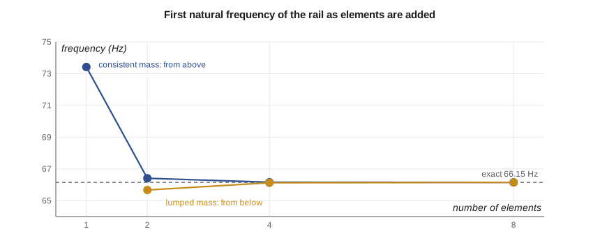
With one consistent element the first frequency is 73.4 Hz, 11 percent high; with two it is within 0.4 percent, and with four it is essentially exact. The lumped results come from below, 65.7 Hz with two elements, and also converge by four. A lumped model with a single element has no free mass at all, since the element's masses sit at the two supports, which is a useful reminder that lumped models need enough nodes for the mass to move. For lumped beam models the rotation degrees of freedom have no mass, so the program first condenses them out of the stiffness matrix, a step called static condensation that software performs automatically.
The bracketing behavior is useful in practice. If a consistent and a lumped model of the same mesh give frequencies close together, both are probably converged; if they differ widely, the mesh is too coarse for that mode. Higher modes, with more half-waves along the member, need proportionally more elements: as a rule of thumb, at least four to six elements per half-wave of the highest mode of interest.
The TP-80 shaft critical speed
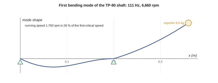
In Lesson 4 the uniform-shaft model gave a stiffness of 4.80 MN/m at the impeller. Treating the 9.5 kg impeller as a single mass on that spring gives a first natural frequency of 113.1 Hz, or 6,785 rpm, the estimate from machine design of about 6,800 rpm. The finite element model, with eight beam elements carrying the shaft's own mass and the impeller as a point mass, gives 111.0 Hz, 6,660 rpm, about two percent lower because the shaft's mass now takes part in the motion. Running speed, 1,760 rpm, is 26 percent of the first critical speed, so the TP-80 is a stiff-shaft machine with a wide margin. For the heavier-duty version, with a longer overhang and a heavier impeller, the margin will shrink, and Owen will repeat the calculation with the stepped geometry, bearing stiffness and, following the vibrations course, an allowance for the water's added mass and the seal's stiffness.
Two masses and the Jacobi method
The last part of the program returns to Lesson 1's spring model, now with masses: the frame top, 120 kg, on its 12 MN/m stiffness, and the 310 kg package on the 8.8 MN/m pads. The 2 by 2 eigenvalue problem is solved by one Jacobi rotation, the classical method that zeros an off-diagonal term of a symmetric matrix by rotating its coordinates; for a 2 by 2 matrix one rotation suffices, while larger matrices need repeated sweeps. The frequencies are 19.6 Hz, mostly the package bouncing on its pads with the frame helping, and 68.7 Hz, the frame and package moving against each other. The single-mass estimate from the vibrations course, 26.8 Hz for the package on its pads alone, was too high because it treated the frame as rigid. Including the frame's flexibility moves the first mode from 26.8 Hz to 19.6 Hz, further below the 29.3 Hz running speed. That eases the near-resonance found in the vibrations course but changes the isolation calculation, and it is a reminder that every component in the load path affects a natural frequency.
Worked problem
Checking a modal model against a test
After the first heavier-duty baseplate is built, Gilles Thériault runs a bump test and measures its first mode at 41.8 Hz, while Owen's model predicted 45.6 Hz. What does the 9 percent difference suggest, and what should Owen check?
Show solution
- Finite element models with converged meshes are usually somewhat too stiff, from idealized joints and supports.
- Likely causes: welded joints modeled as perfectly rigid, isolators or grout stiffness overestimated, or equipment mass placed without its rotary inertia.
- Owen checks the isolator stiffness against the supplier's dynamic value at the test amplitude, and the mass of the motor and its center of gravity.
Answer: A 9 percent overestimate is typical of joint and support idealizations. Updating the isolator stiffness to its dynamic value, a common correction, brings the model to 42.5 Hz, and the corrected model is then used to design the stiffener.
Damping and response
The eigenvalue problem gives frequencies and shapes but not amplitudes. Amplitudes need the damping and the excitation. Damping is rarely modeled element by element; instead, a modal damping ratio is assigned to each mode, typically from test or experience, such as 2 to 5 percent for welded steel structures, as the vibrations course discussed. Harmonic response analysis then gives the amplitude at each frequency of a sinusoidal load such as unbalance, and transient analysis gives the response to a time history such as a start-up or a shock. Both are built on the modes, so a sound modal model, with its frequencies checked, is the foundation of every dynamic analysis.
Common mistakes
MistakeUsing a symmetric half model for a modal analysis.
InsteadModel the full structure or use cyclic symmetry; symmetric models miss antisymmetric modes.
MistakeUsing too few elements per half-wave for higher modes.
InsteadUse at least four to six elements per half-wave of the highest mode of interest.
MistakeLeaving out attached equipment mass.
InsteadAdd motors, impellers and valves as point masses with their rotary inertia where it matters.
MistakeTreating predicted frequencies as exact.
InsteadExpect models to be somewhat stiff; validate the first modes by test when the margin is small.
MistakeForgetting that static condensation is needed for massless rotations in lumped models.
InsteadCondense out massless degrees of freedom, or use consistent mass.
Summary and key terms
- Free vibration leads to the generalized eigenvalue problem Kφ = ω²Mφ; solvers find the lowest modes.
- Consistent mass uses the shape functions, M = ∫ρNᵀN dV; lumped mass places point masses at nodes.
- For the rail, consistent mass gives 73.4, 66.4 and 66.16 Hz with 1, 2 and 4 elements, converging from above to 66.15 Hz; lumped mass converges from below.
- The TP-80 shaft's first critical speed is 6,660 rpm by finite elements against 6,785 rpm for the single-mass estimate; running speed is 26 percent of it.
- The two-mass package model gives 19.6 and 68.7 Hz, showing the effect of the frame's flexibility.
- Validate modal models against tests; joint and support idealizations usually make models too stiff.
- Mass matrix
- The matrix relating nodal accelerations to inertia forces.
- Consistent mass
- A mass matrix derived from the element shape functions.
- Lumped mass
- A diagonal mass matrix with mass concentrated at the nodes.
- Generalized eigenvalue problem
- Kφ = ω²Mφ, giving natural frequencies and mode shapes.
- Mode shape
- The pattern of relative displacement in a natural mode.
- Inverse iteration
- Repeatedly solving Kx = My to converge to the lowest mode.
- Rayleigh quotient
- φᵀKφ/φᵀMφ, an estimate of ω² from a trial shape.
- Lanczos method
- An efficient algorithm used by solvers to find the lowest modes of large models.
- Static condensation
- Eliminating degrees of freedom with no mass or load from the stiffness matrix.
- Critical speed
- A shaft speed equal to a natural frequency of the rotor system.
Practice problems
Work each problem on paper first, then reveal the answer to check.
A 2 kg mass on a 50 kN/m spring: what is its natural frequency?
Show answer
√(50 000/2)/2π = 25.2 Hz.
Write the consistent mass matrix of a bar element of total mass 6 kg.
Show answer
\(\begin{bmatrix} 2 & 1 \\ 1 & 2 \end{bmatrix}\) kg.
From the program, what is the error of the two-element consistent model of the rail?
Show answer
66.41 against 66.15 Hz, about 0.4 percent high.
Why does the finite element critical speed of the shaft come out below the single-mass estimate?
Show answer
The shaft's own mass also moves in the mode, lowering the frequency.
A mode has three half-waves along a member. How many elements would you use along it?
Show answer
At least 12 to 18, four to six per half-wave.
Lesson quiz · 5 questions
Score 60% or more to complete this lesson.
Create a free account to save your progress, take quizzes and earn a certificate.