
MEC-450 · Lesson 4 of 12 · 22 min
Beam and frame elements
Bars and trusses carry load by stretching. Most machine parts carry it by bending: shafts, baseplate rails, brackets, lifting beams. In machine design Owen sized the TP-80 shaft with hand formulas for an overhung beam: the impeller's 1,350 N radial load acting 160 mm beyond the inboard bearing, with the two bearings 200 mm apart, gave bearing reactions of 2,430 N and 1,080 N and a bending moment of 216 N·m at the inboard bearing. Those numbers make an ideal first test for a beam element. A beam element that cannot reproduce them is not worth using on the heavier-duty pump's longer, stepped shaft, where the hand formulas become tedious.
Degrees of freedom of a beam
A beam in a plane deflects sideways, by a transverse displacement v, and its cross-sections rotate, by an angle θ that for small slopes equals dv/dx. To join beam elements so that the deflected shape has no kinks, both v and θ must be continuous between elements. Each node of a beam element therefore has two degrees of freedom, a deflection and a rotation, and the matching nodal loads are a transverse force and a moment. The two-node beam element has four degrees of freedom: \(v_1, \theta_1, v_2, \theta_2\).
With four nodal values, the deflection within the element can be a cubic polynomial, which is exactly the shape of a beam carrying only end forces and moments, as the Euler-Bernoulli equation \(EI\,d^4v/dx^4 = 0\) shows. The cubic shape functions that match one nodal value each, and are zero for the others, are called Hermite cubics:
where \(\xi = x/h\) runs from 0 to 1 along an element of length h. The bending strain energy \(\tfrac12\int EI(v'')^2\,dx\) leads, after integration, to the beam element stiffness matrix
Each column has a physical meaning. The first column lists the end forces and moments needed to give node 1 a unit deflection while holding the other three degrees of freedom at zero; it is the classical fixed-end result found in any structural analysis text. Because the Hermite cubics are exact solutions for a beam loaded only at its ends, the beam element, like the bar, is exact for point loads applied at nodes. Distributed loads are converted into consistent nodal forces and moments, \(qh/2\) and \(\pm qh^2/12\) for a uniform load, and with those the nodal values remain exact while the deflection between nodes is approximate.
The TP-80 shaft as a beam
Owen idealizes the shaft as a uniform 35 mm steel bar, a simplification since the real shaft is stepped, but a good one for testing the element against a closed-form answer. He places nodes at the outboard bearing (x = 0), midway between the bearings, at the inboard bearing (x = 0.200 m), midway along the overhang, and at the impeller (x = 0.360 m). The bearings are modeled as simple supports: zero transverse displacement, with rotation free, since a single-row ball bearing allows a small slope. The impeller load of 1,350 N acts downward at the last node.
# Beam and frame elements: the TP-80 shaft as an overhung beam, and an L-shaped bracket as a plane frame
import math
def solve(A, b):
    n = len(b); A = [r[:] for r in A]; b = b[:]
    for k in range(n):
        p = max(range(k, n), key=lambda i: abs(A[i][k])); A[k], A[p] = A[p], A[k]; b[k], b[p] = b[p], b[k]
        for i in range(k + 1, n):
            f = A[i][k] / A[k][k]
            for j in range(k, n): A[i][j] -= f * A[k][j]
            b[i] -= f * b[k]
    x = [0.0] * n
    for i in range(n - 1, -1, -1): x[i] = (b[i] - sum(A[i][j] * x[j] for j in range(i + 1, n))) / A[i][i]
    return x
def beam_k(EI, h):
    c = EI / h**3
    return [[12*c, 6*h*c, -12*c, 6*h*c], [6*h*c, 4*h*h*c, -6*h*c, 2*h*h*c],
            [-12*c, -6*h*c, 12*c, -6*h*c], [6*h*c, 2*h*h*c, -6*h*c, 4*h*h*c]]

# 1. Shaft idealized as uniform 35 mm steel: bearings at x = 0 (outboard) and 0.200 m (inboard), impeller at 0.360 m
E = 200e9; d = 0.035; I = math.pi * d**4 / 64; EI = E * I; P = 1350.0
xs = [0.0, 0.100, 0.200, 0.280, 0.360]               # nodes: two elements between bearings, two in the overhang
n = len(xs); K = [[0.0] * (2*n) for _ in range(2*n)]
for e in range(n - 1):
    ke = beam_k(EI, xs[e+1] - xs[e]); idx = [2*e, 2*e+1, 2*e+2, 2*e+3]
    for a in range(4):
        for b in range(4): K[idx[a]][idx[b]] += ke[a][b]
F = [0.0] * (2*n); F[2*(n-1)] = -P                     # impeller load downward at the last node
fixed = [0, 4]                                         # vertical displacement zero at both bearings (rotation free)
free = [i for i in range(2*n) if i not in fixed]
uf = solve([[K[a][b] for b in free] for a in free], [F[a] for a in free])
u = [0.0] * (2*n)
for i, v in zip(free, uf): u[i] = v
R = [sum(K[r][m] * u[m] for m in range(2*n)) - F[r] for r in fixed]
a, Lb = 0.160, 0.200
exact = P * a**2 * (Lb + a) / (3 * EI)
print(f"I = {I*1e8:.3f} x 10^-8 m^4, EI = {EI:.0f} N m^2")
print(f"Impeller deflection: FE {1e3*u[2*(n-1)]:.4f} mm, closed form {-1e3*exact:.4f} mm")
print(f"Bearing reactions: outboard {R[0]:.0f} N, inboard {R[1]:.0f} N")
print(f"Deflection midway along the overhang (x = 0.280 m): {1e3*u[6]:.4f} mm; slope at inboard bearing {1e3*u[5]:.4f} mrad")
print(f"Tip stiffness {P/exact/1e6:.3f} MN/m")

# 2. Plane frame: vertical post 0.50 m (fixed at the base) and horizontal arm 0.40 m, 2.0 kN down at the tip
Ef, Af, If = 200e9, 5.6e-4, 2.5e-7
def frame_k(x1, y1, x2, y2):
    Le = math.hypot(x2 - x1, y2 - y1); c, s = (x2 - x1)/Le, (y2 - y1)/Le
    ea, ei = Ef*Af/Le, Ef*If/Le**3
    kl = [[ea, 0, 0, -ea, 0, 0], [0, 12*ei, 6*Le*ei, 0, -12*ei, 6*Le*ei], [0, 6*Le*ei, 4*Le*Le*ei, 0, -6*Le*ei, 2*Le*Le*ei],
          [-ea, 0, 0, ea, 0, 0], [0, -12*ei, -6*Le*ei, 0, 12*ei, -6*Le*ei], [0, 6*Le*ei, 2*Le*Le*ei, 0, -6*Le*ei, 4*Le*Le*ei]]
    T = [[c, s, 0, 0, 0, 0], [-s, c, 0, 0, 0, 0], [0, 0, 1, 0, 0, 0], [0, 0, 0, c, s, 0], [0, 0, 0, -s, c, 0], [0, 0, 0, 0, 0, 1]]
    return [[sum(T[k][i] * kl[k][l] * T[l][j] for k in range(6) for l in range(6)) for j in range(6)] for i in range(6)]
pts = [(0, 0), (0, 0.5), (0.4, 0.5)]
K = [[0.0] * 9 for _ in range(9)]
for e in range(2):
    ke = frame_k(*pts[e], *pts[e+1]); idx = list(range(3*e, 3*e + 6))
    for a in range(6):
        for b in range(6): K[idx[a]][idx[b]] += ke[a][b]
F = [0.0] * 9; F[7] = -2000.0
uf = solve([r[3:] for r in K[3:]], F[3:])
h, arm, Pf = 0.5, 0.4, 2000.0
v_hand = Pf*arm**3/(3*Ef*If) + Pf*arm**2*h/(Ef*If) + Pf*h/(Ef*Af)
u_hand = Pf*arm*h**2/(2*Ef*If)
print(f"\nFrame tip: FE ux {1e3*uf[3]:.4f} mm, uy {1e3*uf[4]:.4f} mm; hand calculation ux {1e3*u_hand:.4f}, uy {-1e3*v_hand:.4f} mm")I = 7.366 x 10^-8 m^4, EI = 14732 N m^2 Impeller deflection: FE -0.2815 mm, closed form -0.2815 mm Bearing reactions: outboard -1080 N, inboard 2430 N Deflection midway along the overhang (x = 0.280 m): -0.1173 mm; slope at inboard bearing -0.9774 mrad Tip stiffness 4.796 MN/m Frame tip: FE ux 2.0000 mm, uy -4.0623 mm; hand calculation ux 2.0000, uy -4.0623 mm
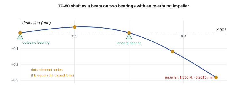
The program reproduces everything Owen calculated by hand. The impeller deflects 0.2815 mm, matching the formula \(Pa^2(L + a)/3EI\) for an overhung beam to all four digits shown. The bearing reactions are 2,430 N at the inboard bearing, upward, and 1,080 N at the outboard bearing, downward: the outboard bearing holds the shaft down as it pivots over the inboard one. The slope at the inboard bearing is 0.98 milliradians, a number worth knowing, because a deep-groove ball bearing tolerates a misalignment of only a few milliradians before its life suffers, and the inboard bearing of the real pump must accept it.
The tip stiffness, 4.80 MN/m, will reappear in Lesson 11. Combined with the impeller's 9.5 kg, it gives a first estimate of the shaft's critical speed, and a beam model that includes the shaft's own mass gives a better one. Seeing the same numbers appear in static, dynamic and hand calculations is part of how an engineer builds confidence in a model.
The real shaft is stepped, with larger diameters at the bearing seats and the seal, which makes it much stiffer than the uniform idealization; in machine design Owen found 56 µm at the seal for the original layout. Modeling the steps is simple with beam elements: put a node at every change of diameter and give each element its own I. That is the main practical advantage over hand formulas, which become laborious for more than two or three steps. For the heavier-duty pump's shaft, which has seven diameters, Owen builds exactly such a model and checks its uniform-diameter case against the result above first.
Frame elements
A frame member both bends and stretches, so a plane frame element combines the bar and beam elements: each node has an axial displacement, a transverse displacement and a rotation, three degrees of freedom, and the element has six. In the element's own axes the 6 by 6 stiffness matrix is the bar matrix in the axial terms and the beam matrix in the bending terms, with no coupling between them for small deflections. To assemble members at different angles, the matrix is transformed to global axes, \(k = T^{\mathsf{T}}k'T\), as for the truss, with T now rotating both translations at each node and leaving the rotation unchanged.
Frame elements are the right idealization when joints are rigid and members slender: building frames, machine skids, welded brackets with stocky members, motor stools. The program's second model is the motor stool bracket of the heavier-duty pump in its simplest form, an L-shaped frame with a 0.50 m vertical post fixed at its base and a 0.40 m horizontal arm, carrying 2.0 kN at the arm's tip. The section has an area of 5.6 × 10⁻⁴ m² and a second moment of area of 2.5 × 10⁻⁷ m⁴.
The hand calculation for this frame has three contributions to the tip's vertical deflection: bending of the arm as a cantilever, \(Pa^3/3EI\); rotation of the post's top, which swings the whole arm down, \(Pa^2h/EI\); and axial shortening of the post, \(Ph/EA\). The post's bending also moves the tip horizontally by \(Pah^2/2EI\). The program gives a horizontal deflection of 2.000 mm and a vertical deflection of 4.062 mm, matching the hand results exactly. The vertical deflection is dominated by the post's rotation, 3.20 mm of the total, a reminder that in a frame the members flex each other.
Worked problem
Where to stiffen the motor bracket
Farah wants the tip deflection of the L-bracket below 2 mm. Using the hand breakdown, which member should be stiffened, and by how much?
Show solution
- Arm bending: \(Pa^3/3EI = 2000 \times 0.064/(3 \times 200 \times 10^9 \times 2.5 \times 10^{-7}) = 0.853\) mm.
- Post rotation: \(Pa^2h/EI = 2000 \times 0.16 \times 0.5/(50\,000) = 3.20\) mm.
- Post shortening is negligible, about 0.009 mm.
- Doubling the post's I halves its contribution to 1.60 mm, giving about 2.46 mm in all; tripling it gives 1.07 + 0.85 = 1.92 mm.
Answer: The post needs about three times its present second moment of area; stiffening the arm alone could never meet the target. Breaking a frame's deflection into contributions is a quick way to see where material does the most good.
Limitations of beam elements
The Euler-Bernoulli beam assumes that plane sections stay plane and perpendicular to the neutral axis, so it ignores shear deformation. For long, slender members that is excellent, but for short, deep beams, such as a stubby shaft between closely spaced bearings, shear deflection becomes significant. Software offers Timoshenko beam elements that include it; when the span is less than about five times the depth, the difference is worth checking. Beam elements also say nothing about local stresses at fillets, holes, keyways and welds. They give the nominal bending moment, which is then multiplied by a stress concentration factor, exactly as in machine design. Where the geometry is too complicated for a handbook factor, a two- or three-dimensional model of the detail is needed, as in Lessons 6 to 9.
The connections between members are another idealization. A beam model joins members at points, while real joints have finite size, and welded or bolted joints are neither perfectly rigid nor perfectly pinned. For skids and brackets the usual approach is to model the joints as rigid, check the results for sensitivity, and use detailed solid models only for joints whose stresses matter.
Common mistakes
MistakeRestraining the rotation at a bearing that allows the shaft to tilt.
InsteadModel a single ball bearing as a simple support; restrain rotation only where the support really prevents it.
MistakeUsing one element for a stepped shaft.
InsteadPlace a node at every change of section and give each element its own I.
MistakeReading local stresses at fillets directly from a beam model.
InsteadBeam elements give nominal stress; apply a stress concentration factor or model the detail.
MistakeIgnoring shear deformation in short, deep beams.
InsteadUse Timoshenko elements, or check, when the span is less than about five times the depth.
MistakeAssembling frame members without transforming their matrices.
InsteadTransform each element from local to global axes before assembly.
Summary and key terms
- A beam node has a deflection and a rotation; the two-node beam element uses Hermite cubic shape functions.
- The beam element is exact for loads at nodes; consistent nodal loads represent distributed loads.
- The uniform-shaft model reproduces the 0.2815 mm impeller deflection and the 2,430 N and 1,080 N bearing reactions.
- A plane frame element combines bar and beam behavior with three degrees of freedom per node.
- The L-bracket's tip moves 2.000 mm across and 4.062 mm down, mostly from rotation of the post.
- Beam models give nominal stresses and ignore shear deformation; local details need other elements.
- Beam element
- A two-node element carrying bending, with deflection and rotation at each node.
- Hermite cubic
- A cubic shape function matching a nodal deflection or rotation.
- Rotation degree of freedom
- The slope of the beam at a node, dv/dx for small slopes.
- Frame element
- An element combining axial and bending behavior, with three degrees of freedom per node in a plane.
- Simple support
- A support that prevents deflection but allows rotation.
- Fixed support
- A support that prevents both deflection and rotation.
- Euler-Bernoulli beam
- Beam theory in which plane sections remain plane and normal to the neutral axis, ignoring shear deformation.
- Timoshenko beam
- Beam theory that includes shear deformation and rotary inertia.
- Nominal stress
- Stress calculated from beam theory without local concentration effects.
- Overhung load
- A load applied beyond a support, as with an end-suction pump impeller.
Practice problems
Work each problem on paper first, then reveal the answer to check.
A cantilever 0.5 m long, EI = 20 kN·m², carries 1 kN at its tip. What is the tip deflection?
Show answer
PL³/3EI = 1000 × 0.125/60 000 = 2.08 mm.
What are the consistent nodal loads for a uniform load of 2 kN/m on a 0.3 m beam element?
Show answer
0.3 kN at each node and moments of ±2000 × 0.09/12 = ±15 N·m.
From the program, what is the deflection midway along the overhang?
Show answer
0.117 mm downward.
Why does the outboard bearing reaction of the TP-80 shaft act downward?
Show answer
The shaft pivots over the inboard bearing, so the outboard end tends to lift and must be held down.
How many degrees of freedom does a plane frame model with 10 nodes have before supports are applied?
Show answer
30.
Lesson quiz · 5 questions
Score 60% or more to complete this lesson.
Create a free account to save your progress, take quizzes and earn a certificate.