
MEC-395 · Lesson 7 of 12 · 22 min
Strain, force and torque measurement
The uncertainty budget of Lesson 3 put torque second only to flow, contributing a third of the variance of efficiency. That makes TQ-301, the in-line torque transducer between the motor and the TP-80, one of the two most important instruments on TL-3. It is also a strain-gauge instrument, and so are the load cells under the weigh tank that calibrates the flowmeter. This lesson explains how strain gauges work, how they are built into force and torque transducers, and how Owen checks TQ-301 against an independent measurement of torque.
Strain and the strain gauge
Strain is the fractional change in length of a material under load, \(\varepsilon = \Delta L/L\). It is a small, dimensionless number, usually quoted in microstrain: one microstrain is a change of one part per million. A steel shaft working at a sensible stress strains by a few hundred microstrain. A bonded foil strain gauge is a thin metal foil, etched into a zigzag grid and backed by a polymer film, glued firmly to the surface of the part. When the surface stretches, the grid's conductors become longer and thinner and their resistance rises; when it compresses, the resistance falls. The relationship is described by the gauge factor:
For the common copper-nickel alloy foils, GF is close to 2. A 350 Ω gauge strained by 500 microstrain therefore changes its resistance by only 0.35 Ω, a tenth of a percent, which is why the bridge circuits of Lesson 5 are essential. The gauge measures the average strain over its grid length, in the direction of its grid lines, and is nearly insensitive to strain across them.
A strain gauge responds to temperature as well as strain, because the foil's resistance changes with temperature and because the foil and the part expand by different amounts. The result, called apparent strain, can be tens of microstrain per degree for an unmatched gauge. Self-temperature-compensated gauges are made with an alloy treated to match the expansion of a particular material, such as steel or aluminum, which reduces apparent strain to a few microstrain per degree over a stated range. Bridges with active gauges in all four arms cancel most of what remains, since all four gauges see the same temperature.
Installing gauges is a skilled job. The surface must be cleaned and abraded, the gauge aligned precisely, the adhesive cured as specified, the leads strain-relieved and the whole installation protected from moisture, which lowers the insulation resistance and makes readings drift. A gauge whose insulation resistance to the part has fallen from thousands of megohms to a few megohms will drift even though its resistance looks normal. Commercial transducers are built under controlled conditions, which is one reason a purchased torque transducer is far more stable than gauges applied in the field.
Rosettes and principal strains
A single gauge measures strain in one direction. When the directions of the principal strains are unknown, as on a pump casing or a bracket, a rosette of three gauges at 0°, 45° and 90°, or at 0°, 60° and 120°, gives enough information to find the principal strains, their directions and, through the material's elastic constants, the principal stresses. The design group uses rosettes when testing new casings under hydrostatic pressure. For a transducer, the loading is known in advance and the gauges can be placed exactly along the principal directions.
Torque transducers
When a solid circular shaft carries a torque T, its surface is in pure shear, with shear stress \(\tau = 16T/(\pi d^3)\). Pure shear is equivalent to equal tension and compression at 45° to the shaft axis, with principal strains of
where G is the shear modulus. A torque transducer is a shaft with a carefully machined measuring section and four gauges at ±45°, two on each side, wired as a full bridge. Two gauges see tension and two compression, so the bridge output is four times that of a single gauge. The arrangement also cancels the effects of bending, which strains gauges on opposite sides equally and oppositely and so produces no bridge output, and of axial load, which strains all four equally.
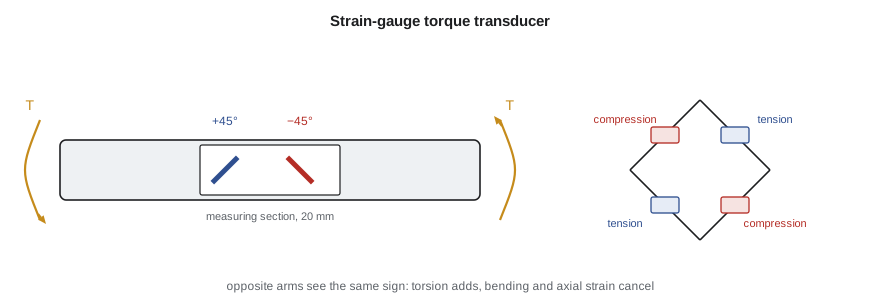
The signal must then cross from a rotating shaft to a stationary housing. Older transducers used slip rings, brushes running on rotating rings, which wear and add electrical noise. Most modern transducers, including TQ-301, use a non-contact link: power is coupled to the rotor inductively, and the bridge signal is digitized on the rotor and transmitted to the stator by a radio-frequency or optical link. Such transducers usually also carry a speed sensor, a toothed ring read by a magnetic or optical pickup, so that torque and speed come from the same instrument.
# Torque and force measurement on TL-3: the in-line torque transducer, a reaction-arm check and the weigh tank
import math
# 1. Strain-gauge torque transducer: solid steel measuring section with four gauges at +/-45 degrees
G, d, GF, Vex = 79.3e9, 0.020, 2.05, 5.0        # shear modulus Pa, section diameter m, gauge factor, excitation V
for T in (25.0, 56.8, 100.0):
    tau = 16*T/(math.pi*d**3)                     # surface shear stress
    eps = tau/(2*G)                               # principal strain at 45 degrees = half the shear strain
    Vo = GF*eps*Vex                               # full bridge, four gauges at +/-eps
    print(f"T = {T:5.1f} N m: shear stress {tau/1e6:5.1f} MPa, strain {eps*1e6:5.0f} microstrain, output {Vo*1000:.3f} mV ({Vo/Vex*1000:.3f} mV/V)")
# Range choice: +/-0.1 % of full scale at the working torque of 56.8 N m
for FS in (200.0, 100.0, 75.0):
    print(f"  full scale {FS:5.0f} N m: +/-{0.001*FS:.3f} N m = {100*0.001*FS/56.8:.2f} % of reading at 56.8 N m")
# 2. Reaction check: motor in trunnion bearings, arm 0.500 m to a load cell
L, F = 0.500, 113.9                               # m, N (load cell reading at the guarantee point)
uL, uF, ufric = 0.0005, 0.06, 0.08               # arm length, load cell and trunnion friction (N m), standard uncertainties
Tr = F*L
uT = math.sqrt((L*uF)**2 + (F*uL)**2 + ufric**2)
print(f"\nReaction torque F x L = {Tr:.2f} N m, standard uncertainty {uT:.3f} N m ({100*uT/Tr:.2f} %)")
print(f"In-line transducer reads 56.80 N m; difference {Tr - 56.80:+.2f} N m, within the combined uncertainty?",
      "yes" if abs(Tr - 56.80) < 2*math.sqrt(uT**2 + 0.0577**2) else "no")
# 3. Weigh tank WT-1 on four 2.0 mV/V load cells of 5,000 kg capacity, summed in a junction box
cap, sens, Vex_w = 4*5000.0, 2.0e-3, 10.0
for m in (0.0, 2000.0, 6000.0):
    print(f"  collected {m:6.0f} kg -> summed output {sens*Vex_w*m/cap*1000:.3f} mV")
# Test-weight check: 1,000 kg of certified weights added; tank indicates 999.3 kg
print(f"Test weights 1000.0 kg, indicated 999.3 kg: span correction factor {1000.0/999.3:.5f}")T = 25.0 N m: shear stress 15.9 MPa, strain 100 microstrain, output 1.029 mV (0.206 mV/V) T = 56.8 N m: shear stress 36.2 MPa, strain 228 microstrain, output 2.337 mV (0.467 mV/V) T = 100.0 N m: shear stress 63.7 MPa, strain 401 microstrain, output 4.114 mV (0.823 mV/V) full scale 200 N m: +/-0.200 N m = 0.35 % of reading at 56.8 N m full scale 100 N m: +/-0.100 N m = 0.18 % of reading at 56.8 N m full scale 75 N m: +/-0.075 N m = 0.13 % of reading at 56.8 N m Reaction torque F x L = 56.95 N m, standard uncertainty 0.103 N m (0.18 %) In-line transducer reads 56.80 N m; difference +0.15 N m, within the combined uncertainty? yes collected 0 kg -> summed output 0.000 mV collected 2000 kg -> summed output 2.000 mV collected 6000 kg -> summed output 6.000 mV Test weights 1000.0 kg, indicated 999.3 kg: span correction factor 1.00070
TQ-301's measuring section is 20 mm in diameter. At its rated 100 N·m the surface shear stress is 64 MPa and the principal strain about 400 microstrain, giving an output of 0.82 mV/V with 5 V excitation. At the TP-80's working torque of 56.8 N·m the strain is 228 microstrain. The program also returns to the question raised in Lesson 3. The transducer's accuracy is ±0.1 percent of full scale, which at 56.8 N·m is 0.18 percent of reading. A 200 N·m transducer, which a cautious buyer might choose for margin, would give 0.35 percent; a 75 N·m transducer, 0.13 percent, but with less margin for the starting transient, when torque briefly reaches about twice the running value. Torque transducers withstand a stated overload, often 150 to 200 percent of rated torque, without damage, so the 100 N·m choice is a sound compromise for the TP-80, though a larger pump on TL-3 would need a larger transducer.
Checking torque by reaction
An in-line transducer is a single instrument, and Marco wants evidence that its readings are right in use, not just on its calibration certificate. A classic independent method is the reaction, or cradle, dynamometer: the motor is mounted in low-friction trunnion bearings so that it can rotate slightly about the shaft axis, and a horizontal arm from the motor frame presses on a load cell. The torque the motor applies to the shaft is reacted by the frame, so \(T = FL\), where F is the load cell force and L the arm length. The method's errors are the arm length, the load cell, and friction in the trunnion bearings, which can be checked by applying known weights to the arm with the motor stopped.
Tidewater's old test stand had a cradled motor, and Gilles has refurbished it for exactly this cross-check. At the guarantee point the load cell reads 113.9 N on a 0.500 m arm, giving 56.95 N·m with a standard uncertainty of 0.10 N·m. TQ-301 reads 56.80 N·m. The difference of 0.15 N·m is well within the combined uncertainty of the two methods, so the cross-check supports TQ-301's calibration. The reaction method is less precise in this setup, mainly because of trunnion friction, but its independence is what makes it valuable: an error common to both readings would be very unlikely.
A third approach, common in factory testing of large pumps, measures the electrical power into the motor and multiplies it by the motor's efficiency, taken from a separate test of the motor. It avoids a torque transducer altogether, but its uncertainty is set by the motor efficiency, which is rarely known better than a few tenths of a percent and varies with load and temperature. The pump test standards allow it, with appropriate uncertainty limits, and some customers specify it. Owen notes it in his report as a fallback if TQ-301 must be sent away for calibration.
Load cells and the weigh tank
A load cell is a force transducer: an elastic element, shaped so that the strain at the gauge positions is proportional to the applied force and insensitive to where and how the force is applied, with gauges in a full bridge. Common shapes include the S-beam, used in tension and compression, the shear beam, which measures shear strain in a web and is insensitive to load position, and the compression canister for large loads. Their sensitivity is typically 2 mV/V at rated capacity.
WT-1, the weigh tank that calibrates FT-201, stands on four shear-beam load cells of 5,000 kg capacity each. Their signals are summed in a junction box, where trimming resistors equalize their sensitivities so that the total reading is independent of where the water's weight falls. With 10 V excitation, the summed output is 1.0 mV per 2,000 kg. The weigh tank's calibration is checked with certified test weights: when 1,000 kg of weights are placed on the tank, it indicates 999.3 kg, and the software applies a span correction factor of 1.00070. Lesson 10 uses the weigh tank to calibrate the flowmeter.
| Effect | Description | Typical size for a good load cell |
|---|---|---|
| Nonlinearity and hysteresis | Departure from a straight line, rising and falling | 0.02 % of rated output |
| Creep | Change of output under constant load over time | 0.02 % in 30 minutes |
| Temperature effect on zero | Zero shift with temperature | 0.002 % of rated output per °C |
| Off-axis loading | Error from side loads or moments | Small if mounting hardware isolates side loads |
| Overload | Safe load without permanent change | 150 % of rated capacity |
Load cells need careful mounting. Side loads from piping, thermal expansion of the tank or misalignment add errors that do not appear in the cell's calibration. WT-1's inlet and outlet pipes are connected through flexible hoses, and Gilles checks that the tank's reading does not change when the outlet valve is operated, a simple test that would reveal pipe forces acting on the tank. Creep, a slow change of output under constant load, matters for the weigh tank because it is read at the start and end of a collection that may last a minute or more; good shear-beam cells creep by a few hundredths of a percent over that time.
Worked problem
Sizing a load cell for a reaction arm
A larger pump to be tested on TL-3 will need up to 250 N·m. The reaction arm is 0.500 m long. Select a load cell capacity if the load cell's accuracy is ±0.03 percent of rated capacity and the target is ±0.1 percent of reading at 150 N·m.
Show solution
- Force at 250 N·m: \(250/0.500 = 500\) N; at 150 N·m, 300 N.
- A 1,000 N cell: ±0.30 N, or 0.10 percent of 300 N, just meeting the target.
- A 500 N cell would be fully loaded at the maximum torque, leaving no margin.
Answer: A cell of about 1,000 N capacity meets the target at 150 N·m and has twice the maximum load as margin. Below 150 N·m its percentage error grows, so for low-torque points a smaller cell or a longer arm would be better.
Common mistakes
MistakeIgnoring apparent strain from temperature in a quarter-bridge gauge.
InsteadUse self-temperature-compensated gauges and full bridges, or a dummy gauge for compensation.
MistakeChoosing a torque transducer with a large full scale for safety.
InsteadAccuracy stated in percent of full scale degrades at the working point; size for the working torque with adequate overload rating.
MistakeTrusting a single torque instrument without any cross-check.
InsteadCheck against an independent method, such as a reaction arm, from time to time.
MistakeRigidly connecting pipes to a weigh tank.
InsteadUse flexible connections and check that operating valves does not change the reading.
MistakeReading a load cell immediately after loading when creep matters.
InsteadAllow for creep or read at consistent times after loading.
Summary and key terms
- A bonded foil strain gauge's resistance changes by GF ε, with GF about 2.
- Torsion of a shaft gives principal strains ±τ/(2G) at 45°; four gauges in a full bridge cancel bending and axial load.
- TQ-301 strains 228 microstrain at the working torque; its ±0.1 percent of full scale is 0.18 percent of reading.
- A reaction-arm check gives 56.95 ± 0.10 N·m against TQ-301's 56.80 N·m, supporting its calibration.
- Load cells are strain-gauge force transducers, typically 2 mV/V; mounting, side loads and creep cause errors.
- The weigh tank is checked with certified test weights; a 1,000 kg check gave a span factor of 1.00070.
- Strain
- Fractional change in length, ΔL/L.
- Microstrain
- A strain of one part per million.
- Gauge factor
- The ratio of fractional resistance change to strain for a strain gauge.
- Apparent strain
- A false strain reading caused by temperature change.
- Rosette
- A group of strain gauges at set angles used to find principal strains.
- Torque transducer
- An instrumented shaft that measures the torque transmitted through it.
- Reaction dynamometer
- A torque measurement made from the reaction force on a machine frame mounted in trunnion bearings.
- Load cell
- A strain-gauge transducer that measures force.
- Creep
- Slow change of a load cell's output under constant load.
- Span correction factor
- A multiplier that corrects an instrument's reading so that it agrees with a reference at a known load.
Practice problems
Work each problem on paper first, then reveal the answer to check.
A 120 Ω gauge with GF 2.1 is strained by 300 microstrain. What is the change in resistance?
Show answer
120 × 2.1 × 300e-6 = 0.0756 Ω.
What principal strain does a 30 mm solid steel shaft (G = 79.3 GPa) show at 200 N·m?
Show answer
τ = 37.7 MPa; ε = 238 microstrain.
In the program, what output in mV/V would TQ-301 give at 56.8 N·m with 10 V excitation?
Show answer
Still 0.467 mV/V, since sensitivity per volt does not depend on excitation; the output would be 4.67 mV.
Why does a full bridge of ±45° gauges not respond to bending of the shaft?
Show answer
Bending strains gauges on opposite sides equally and oppositely, and their effects cancel in the bridge.
Four 5,000 kg load cells with 2.0 mV/V sensitivity are summed with 10 V excitation. What is the output for 8,000 kg?
Show answer
8 mV.
Lesson quiz · 5 questions
Score 60% or more to complete this lesson.
Create a free account to save your progress, take quizzes and earn a certificate.