
MEC-280 · Lesson 5 of 12 · 26 min
Machining fundamentals and cutting mechanics
Almost every part of the KG-40 is machined somewhere. The cast housing has its bores and faces cut; the forged gears have their teeth hobbed; the shafts are turned, splined and drilled. Machining removes material as chips with a sharp, hard tool, and it is the process that produces most of the precise surfaces in mechanical products. It is flexible, accurate and needs little tooling, but it is slower than forming and turns purchased material into chips. Knowing how a tool actually cuts, what forces it meets, how hot it gets and why it wears is the basis for choosing speeds, feeds and tools sensibly. Lead machinist Carla Brandt and Dev Patel start this part of the course with a simple question from Amira: why does the shop run the 4140 shafts at one speed and the gray iron housings at quite another?
The three cutting parameters
Every machining operation is described by three quantities. Cutting speed \(v\) is the speed of the work surface past the tool edge, in meters per minute; on a lathe it is \(v = \pi D N\), with \(D\) the work diameter and \(N\) the spindle speed. Feed \(f\) is how far the tool advances per revolution, in millimeters per revolution, or per tooth for milling cutters. Depth of cut \(d\) is how far the tool penetrates into the work. Their product is the material removal rate, the volume of metal turned into chips per unit time.
Roughing cuts use large feeds and depths to remove material quickly, with speed limited by tool life and machine power. Finishing cuts use small feeds and depths and often higher speeds to achieve accuracy and surface finish. A good process plan removes most of the stock in roughing and leaves a small, uniform allowance, typically 0.3 to 1 mm, for finishing.
Orthogonal cutting and the shear plane
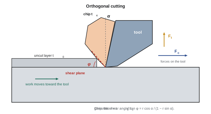
Real tools have complex shapes, but the essential mechanics can be seen in orthogonal cutting: a straight edge perpendicular to the cutting direction, removing a layer of uncut thickness \(t_0\). The tool face that the chip slides along is the rake face, set at the rake angle \(\alpha\) from the perpendicular to the work surface. Below the edge, the flank face is relieved by the clearance angle so that it does not rub the new surface.
The metal does not split ahead of the tool like wood. It is sheared intensely in a narrow zone running from the tool edge up to the free surface, which we idealize as a shear plane at the shear angle \(\phi\). The sheared metal becomes the chip, which is thicker than the uncut layer, \(t_c > t_0\). The chip thickness ratio \(r = t_0/t_c\) is measured from the chips, and geometry then gives the shear angle.
The shear strain \(\gamma\) in the chip, given by the second expression, is typically 2 to 5, far larger than any tensile test reaches, and it happens in microseconds. That is why machining needs so much energy per unit volume and why the chip comes off hot and hard.
Cutting forces and Merchant's model
A dynamometer under the tool measures two forces: the cutting force \(F_c\) in the cutting direction and the thrust force \(F_t\) perpendicular to it. Resolving these along the rake face gives the friction force \(F\) and normal force \(N\) on the chip, and along the shear plane gives the shear force \(F_s\) and the normal force on the shear plane. The friction coefficient on the rake face and the shear stress in the shear plane follow.
Eugene Merchant argued in the 1940s that the shear plane forms at the angle that minimizes the energy needed, which gives a simple relation between shear angle, rake angle and friction angle \(\beta\). It shows the right trends: a larger rake angle and lower friction raise the shear angle, thin the chip and reduce the force and power. The model overpredicts the shear angle in many real cuts, so engineers use it for understanding and use measured data or specific energies for design.
Worked problem
Forces from a test cut on 4140
In an orthogonal test on annealed 4140 steel, a tool with a 10° rake angle removes a layer 0.25 mm thick and 3.0 mm wide. The chip measures 0.70 mm thick. The dynamometer reads \(F_c = 1550\ \text{N}\) and \(F_t = 690\ \text{N}\). Find the shear angle, the friction coefficient and the shear stress, and compare the shear angle with Merchant's prediction.
Show solution
- Chip ratio \(r = 0.25/0.70 = 0.357\); \(\tan\phi = 0.357\cos 10°/(1 - 0.357\sin 10°) = 0.375\), so \(\phi = 20.6°\).
- Rake face forces: \(F = 1550\sin 10° + 690\cos 10° = 949\ \text{N}\); \(N = 1550\cos 10° - 690\sin 10° = 1407\ \text{N}\); \(\mu = 0.67\), \(\beta = 34.0°\).
- Shear force \(F_s = 1550\cos 20.6° - 690\sin 20.6° = 1209\ \text{N}\); shear plane area \(= t_0 w/\sin\phi = 0.75/0.351 = 2.14\ \text{mm}^2\); \(\tau_s = 566\ \text{MPa}\).
- Merchant: \(\phi = 45 + 5 - 17.0 = 33.0°\), about 12° higher than measured.
Answer: The shear stress of about 570 MPa reflects the heavy strain hardening in the shear zone, well above the shear strength of the annealed bar. The specific energy is \(1550/(0.25 \times 3.0) = 2.1\ \text{J/mm}^3\). As often happens, Merchant's model predicts too large a shear angle; the measured value is the one to use.
Specific cutting energy and power
The power consumed in cutting is the cutting force times the cutting speed, \(P_c = F_c v\). Dividing by the material removal rate gives the specific cutting energy \(u\), the energy to remove a unit volume, in J/mm³ or equivalently in N/mm² of chip cross-section. It depends mainly on the work material, rising somewhat as the uncut chip thickness gets smaller because of edge effects. Approximate values are 0.4 to 1.1 J/mm³ for aluminum alloys, 1.1 to 2.0 for gray cast iron, 2.0 to 4.0 for carbon and alloy steels, 3 to 5 for stainless steels and 3 to 6 for titanium alloys. With a value of \(u\), the force and power for a planned cut follow immediately, and the machine's spindle power sets a limit on how aggressive the roughing can be.
| Work material | Specific energy u (J/mm³) | Typical cutting speed, carbide (m/min) | Typical cutting speed, HSS (m/min) |
|---|---|---|---|
| Aluminum alloys | 0.4 to 1.1 | 300 to 1000+ | 100 to 300 |
| Gray cast iron | 1.1 to 2.0 | 120 to 250 | 20 to 40 |
| Low-carbon steel | 2.0 to 3.0 | 150 to 300 | 25 to 45 |
| Alloy steel, annealed (4140) | 2.0 to 3.5 | 120 to 250 | 18 to 30 |
| Stainless steel (austenitic) | 3.0 to 5.0 | 100 to 200 | 12 to 25 |
| Titanium alloys | 3.0 to 6.0 | 40 to 90 | 8 to 15 |
Heat and temperature
Nearly all the energy of cutting turns into heat, generated in the primary shear zone and by friction where the chip slides on the rake face. Most of it leaves with the chip, which is why chips glow blue on steel; a smaller share goes into the tool and the work. Tool temperatures at the rake face reach 600 to 1000 °C in steel cutting at production speeds. Temperature rises with cutting speed and, more weakly, with feed, roughly as \(T \propto v^{0.4} f^{0.2}\) in some models. Because tool materials soften and wear faster as they get hotter, temperature is what ultimately limits cutting speed.
Tool wear and Taylor's tool life equation
A cutting edge wears in several ways. Flank wear is a land worn on the clearance face by abrasion against the new surface; it grows steadily and is the usual criterion for tool life, often set at a width of 0.3 mm for carbide in finishing. Crater wear is a depression worn into the rake face by diffusion and chemical reaction with the hot chip. Notching occurs at the depth-of-cut line, where the work's hard surface skin or a work-hardened layer abrades the edge. Edges can also chip, crack from thermal cycling in interrupted cuts, or fail suddenly by plastic deformation when overloaded.
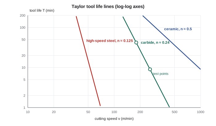
In 1907 Frederick Taylor published the results of years of experiments showing that tool life falls steeply as speed rises, following a power law. With tool life \(T\) in minutes and cutting speed \(v\), the relation is a straight line on log-log axes.
The exponent \(n\) depends mainly on the tool material, roughly 0.1 to 0.15 for high-speed steel, 0.2 to 0.3 for carbide and 0.4 to 0.6 for ceramics. The constant \(C\) is the cutting speed that gives a one-minute life and depends on the work material, feed, depth and the wear criterion. A small \(n\) means life is very sensitive to speed: for high-speed steel, a 10 percent speed increase can halve tool life. Extended forms add feed and depth, \(v T^n f^a d^b = K\).
Worked problem
Finding Taylor constants for the shaft turning
Tests turning 4140 with a coated carbide insert at a fixed feed and depth gave a tool life of 42 min at 180 m/min (590 sfm) and 9 min at 260 m/min (853 sfm). Find n and C, and the speed for a 25 min tool life.
Show solution
- Taking logs of \(v_1 T_1^n = v_2 T_2^n\): \(n = \ln(v_2/v_1)/\ln(T_1/T_2) = \ln(1.444)/\ln(4.667) = 0.239\).
- \(C = 180(42)^{0.239} = 180(2.443) = 440\ \text{m/min}\).
- For \(T = 25\ \text{min}\): \(v = 440/25^{0.239} = 440/2.159 = 204\ \text{m/min}\).
Answer: About 204 m/min (669 sfm) gives a 25 minute life. In Lesson 6 we use these constants to find the speed that minimizes cost per part.
# Cutting mechanics for 4140 steel: test cut analysis and tool life
import math

# Orthogonal test cut
alpha = math.radians(10)       # rake angle
t0, tc, w = 0.25, 0.70, 3.0    # mm: uncut thickness, chip thickness, width
Fc, Ft = 1550.0, 690.0         # N: cutting and thrust forces

r = t0 / tc
phi = math.atan(r * math.cos(alpha) / (1 - r * math.sin(alpha)))
F = Fc * math.sin(alpha) + Ft * math.cos(alpha)      # friction force on rake face
N = Fc * math.cos(alpha) - Ft * math.sin(alpha)      # normal force on rake face
mu = F / N
beta = math.atan(mu)
Fs = Fc * math.cos(phi) - Ft * math.sin(phi)         # shear force on shear plane
As = t0 * w / math.sin(phi)                          # shear plane area, mm^2
gamma = 1 / math.tan(phi) + math.tan(phi - alpha)    # shear strain
phi_merchant = math.radians(45) + alpha / 2 - beta / 2

print(f"Chip ratio r = {r:.3f}, shear angle = {math.degrees(phi):.1f} deg, shear strain = {gamma:.2f}")
print(f"Rake face: F = {F:.0f} N, N = {N:.0f} N, mu = {mu:.2f} (beta = {math.degrees(beta):.1f} deg)")
print(f"Shear plane: Fs = {Fs:.0f} N on {As:.2f} mm^2, shear stress = {Fs/As:.0f} MPa")
print(f"Merchant's predicted shear angle = {math.degrees(phi_merchant):.1f} deg")

# Specific energy and power at the test conditions, v = 150 m/min
v = 150.0                                    # m/min
mrr = v * 1000 * t0 * w / 60                 # mm^3/s
P = Fc * v / 60                              # W
print(f"\nAt {v:.0f} m/min: power = {P:.0f} W, MRR = {mrr:.0f} mm^3/s, u = {P/mrr:.2f} J/mm^3")

# Taylor constants from two tool-life tests
(v1, T1), (v2, T2) = (180.0, 42.0), (260.0, 9.0)
n = math.log(v2 / v1) / math.log(T1 / T2)
C = v1 * T1 ** n
print(f"\nTaylor fit: n = {n:.3f}, C = {C:.0f} m/min")
print(" v (m/min)  tool life (min)")
for v in (150, 180, 204, 230, 260, 300):
print(f"{v:10d} {(C / v) ** (1 / n):15.1f}")Chip ratio r = 0.357, shear angle = 20.6 deg, shear strain = 2.85
Rake face: F = 949 N, N = 1407 N, mu = 0.67 (beta = 34.0 deg)
Shear plane: Fs = 1209 N on 2.14 mm^2, shear stress = 566 MPa
Merchant's predicted shear angle = 33.0 deg
At 150 m/min: power = 3875 W, MRR = 1875 mm^3/s, u = 2.07 J/mm^3
Taylor fit: n = 0.239, C = 439 m/min
v (m/min) tool life (min)
150 90.1
180 42.0
204 24.9
230 15.0
260 9.0
300 4.9Tool materials
Cutting tools need hardness at high temperature, toughness to resist chipping, and chemical stability against the work. No material excels in all three, so there is a ladder of choices. High-speed steel, alloyed with tungsten, molybdenum, vanadium and cobalt, is tough and easy to grind sharp; it is still used for drills, taps, broaches and form tools, but limited to modest speeds. Cemented carbides, tungsten carbide particles bonded with cobalt, are much harder and keep their hardness to higher temperatures; they are the workhorse of production machining, supplied as replaceable indexable inserts. Most carbide inserts are coated with thin layers of titanium nitride, titanium carbonitride or aluminum oxide by vapor deposition, which resist crater wear and raise permissible speeds by 50 percent or more.
Beyond carbide, ceramics based on alumina or silicon nitride cut cast iron and hardened steel at very high speeds but are brittle. Cubic boron nitride, the second hardest material known, is used for hard turning of hardened steels at 50 to 65 HRC, replacing grinding in some jobs. Polycrystalline diamond excels on aluminum, copper, composites and abrasive nonmetals but reacts with iron at high temperature and so cannot cut steel.
Cutting fluids, chips and machinability
Cutting fluids cool the tool and work, lubricate the chip-tool interface at low speeds, flush chips away and protect the machined surface from rust. Water-based emulsions and synthetic fluids are best for cooling; straight oils lubricate better for tapping, broaching and gear cutting. Minimum-quantity lubrication sprays a tiny amount of oil into an air stream and avoids large fluid systems; dry machining is common for cast iron. Fluids must be maintained to control bacteria, and mist must be extracted, because inhaling metalworking fluid mist can cause respiratory illness and skin contact can cause dermatitis.
Chip form matters too. Long, continuous ribbons from ductile steels tangle around the work and the tool and are dangerous to handle, so inserts carry chip breakers that curl the chip until it snaps. Gray iron forms short, discontinuous chips naturally. Machinability, a loose term for how easily a material machines, combines tool life, surface finish, chip control and power. It is improved by additions such as sulfur and lead in free-machining steels, and by heat treatment to a moderate hardness.
This answers Amira's question. Gray iron's graphite flakes break the chip, lubricate the cut and lower the specific energy, so the housing can be machined fast with modest power, though the iron's abrasive carbides limit tool life. The 4140 shafts need more energy per cubic millimeter, form long chips that need chip breakers, and run at speeds set by the carbide tool life found from Taylor's equation.
Common mistakes
MistakeTreating the chip as the same thickness as the uncut layer.
InsteadChips are thicker; the ratio r = t₀/t_c gives the shear angle.
MistakeApplying Merchant's equation as an exact prediction.
InsteadIt shows trends but often overpredicts φ; use measured chip ratios or forces for design.
MistakeForgetting the motor efficiency when checking spindle power.
InsteadDivide cutting power by the machine efficiency, typically 0.75 to 0.9.
MistakeAssuming a small speed increase barely affects tool life.
InsteadWith n = 0.25, a 20 % speed increase cuts tool life by about half; with n = 0.125, by three quarters.
MistakeUsing diamond tools on steel.
InsteadDiamond reacts with iron at cutting temperatures; use carbide, ceramic or CBN for ferrous metals.
Summary and key terms
- Cutting speed, feed and depth define a cut; MRR = vfd.
- Metal shears along a shear plane at angle φ; tan φ = r cos α/(1 − r sin α), with r = t₀/t_c.
- Merchant's model, φ = 45° + α/2 − β/2, explains how rake angle and friction affect forces.
- Cutting power P = F_c v = u·MRR, with specific energy u depending mainly on the work material.
- Heat concentrates at the rake face and limits cutting speed; tools wear by flank wear, cratering, notching and chipping.
- Taylor's equation vTⁿ = C links tool life and speed; n is about 0.125 for HSS, 0.25 for carbide and 0.5 for ceramics.
- Cutting speed
- The speed of the work surface past the cutting edge.
- Feed
- The tool advance per revolution or per tooth.
- Material removal rate
- The volume of material removed per unit time, vfd.
- Rake angle
- The angle of the tool face along which the chip flows.
- Shear angle
- The angle of the plane along which the work material shears to form the chip.
- Chip thickness ratio
- The uncut thickness divided by the chip thickness.
- Specific cutting energy
- The energy needed to remove a unit volume of material.
- Flank wear
- Wear on the clearance face of the tool, rubbing against the new surface.
- Crater wear
- A hollow worn into the rake face by the hot chip.
- Taylor tool life equation
- vTⁿ = C, relating cutting speed and tool life.
- Chip breaker
- A tool feature that curls and breaks the chip into short pieces.
Practice problems
Work each problem on paper first, then reveal the answer to check.
A 60 mm bar turns at 800 rpm with f = 0.25 mm/rev and d = 2 mm. Find v and MRR.
Show answer
v = π(0.060)(800) = 151 m/min; MRR = 151 000 × 0.25 × 2 = 75 400 mm³/min.
With u = 3.0 J/mm³ and 85 % motor efficiency, what motor power does that cut need?
Show answer
P_c = 3.0 × 75 400/60 = 3770 W; motor 4.4 kW.
A 0° rake tool gives a chip ratio of 0.35. Find the shear angle.
Show answer
tan φ = 0.35, φ = 19.3°.
For n = 0.25 and C = 400 m/min, find tool life at 250 m/min.
Show answer
T = (400/250)⁴ = 6.6 min.
Why is CBN, not diamond, used to turn hardened steel?
Show answer
Diamond reacts with iron at cutting temperatures; CBN is stable against ferrous metals.
In the program, change the rake angle to 0° with the same forces and chip ratio. What happens to the friction coefficient?
Show answer
F = F_t = 690 N, N = F_c = 1550 N, so μ falls to 0.45.
Lesson quiz · 5 questions
Score 60% or more to complete this lesson.
Create a free account to save your progress, take quizzes and earn a certificate.