
MEC-280 · Lesson 3 of 12 · 25 min
Bulk forming: rolling, forging and extrusion
The KG-40 output shaft and its two gears begin as round bar of 4140 chromium-molybdenum steel. In Lesson 1 the cost model showed that forging the gear blanks beats machining them from bar at the planned volume. This lesson explains why forging also makes better gears, and how engineers estimate the forces that rolling mills, forging presses and extrusion presses must supply. Deformation processes shape metal in the solid state by plastic flow. They waste little material, they can be very fast, and by working the metal they refine its grain structure and align it with the part's shape.
Plastic flow, flow stress and strain rate
In MEC-250 we described a metal's stress-strain curve: elastic up to the yield stress, then plastic with strain hardening until necking. Forming processes use the plastic region. Because forming strains are large, engineers work with true stress and true strain. During cold working, the stress needed to keep the metal flowing, the flow stress, rises with strain according to the power law met in MEC-250.
Here \(K\) is the strength coefficient and \(n\) the strain-hardening exponent. Because the flow stress changes during a forming operation, force calculations often use the average flow stress \(\bar\sigma_f\) over the strain from zero to the final value, given by the second expression. For a bar compressed from height \(h_0\) to \(h\), the true strain is \(\varepsilon = \ln(h_0/h)\).
Temperature changes everything. Cold working, near room temperature, gives the best accuracy and surface finish and strengthens the metal by strain hardening, but it needs large forces and limits how much deformation is possible before the metal cracks. Hot working, above about 0.6 of the melting temperature in kelvin, is done while the metal recrystallizes as it deforms, so it does not harden; flow stress is low, ductility is high and very large shape changes are possible. The penalties are scale on the surface, poorer tolerances and the energy to heat the work. Warm working, in between, trades some of each.
In hot working, flow stress depends on strain rate rather than strain: deforming faster requires more stress. A simple model is \(\sigma_f = C\dot\varepsilon^{m}\), where \(m\) is the strain-rate sensitivity, around 0.05 to 0.3 for hot steel. A hydraulic press squeezes slowly; a mechanical press or a hammer deforms much faster and so meets a higher flow stress, though the short contact time also means less heat is lost to the dies.
Rolling
Rolling reduces the thickness of a slab, plate or bar by passing it between rotating rolls. It is the highest-volume metal process in the world: almost all steel and aluminum passes through rolling mills, first hot, from cast slabs to plate, strip and structural shapes, and often then cold, to thin sheet with a bright finish and tight thickness tolerance. Shape rolling with grooved rolls makes bars, rails, I-beams and the round bar Kestrel Drive Systems buys. Thread rolling and ring rolling are variations used directly on parts.
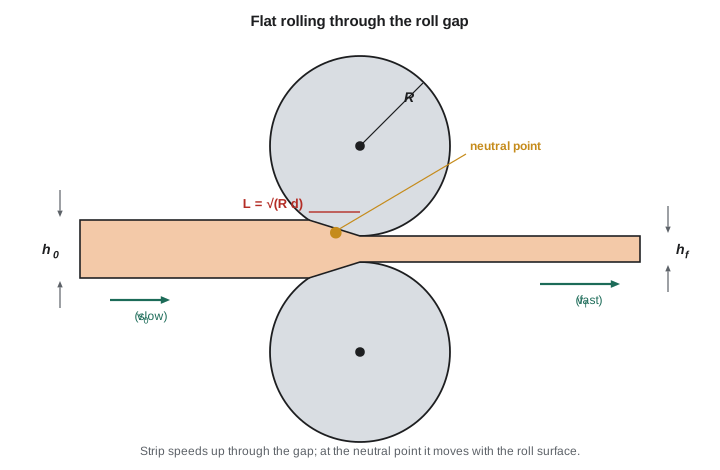
In flat rolling, a strip of thickness \(h_0\) enters the gap and leaves with thickness \(h_f\). The draft is \(d = h_0 - h_f\). Because volume is constant and the width barely changes, the strip must speed up as it thins, so it enters slower than the roll surface and leaves faster. At one point in the contact arc, the neutral point, strip and roll move at the same speed. Friction pulls the strip into the gap on the entry side and resists it on the exit side. If the draft is too large for the friction available, the rolls simply slip; the maximum draft is roughly \(\mu^2 R\), where \(\mu\) is the coefficient of friction and \(R\) the roll radius.
A simple estimate of the roll separating force \(F\) multiplies the average flow stress by the contact area, the width \(w\) times the projected contact length \(L\). Friction raises the true force above this, often by 20 percent or more, which is one reason mills use large backup rolls behind smaller work rolls. The power for a pair of rolls follows from treating \(F\) as acting halfway along the contact length on each roll, as in the third expression, with \(N\) in revolutions per minute.
Worked problem
Cold rolling a spring steel strip
A strip of annealed low-carbon steel 300 mm wide and 25 mm thick is cold rolled to 22 mm in one pass with rolls of 250 mm radius turning at 50 rpm. For this steel \(K = 530\ \text{MPa}\) and \(n = 0.26\). Estimate the roll force and power.
Show solution
- Draft \(d = 3\ \text{mm}\); contact length \(L = \sqrt{250(3)} = 27.4\ \text{mm}\).
- True strain \(\varepsilon = \ln(25/22) = 0.128\); average flow stress \(\bar\sigma_f = 530(0.128)^{0.26}/1.26 = 246\ \text{MPa}\).
- Force \(F = 246(300)(27.4) = 2.02 \times 10^6\ \text{N} \approx 2.0\ \text{MN}\).
- Power \(P = 2\pi(50)(2.02 \times 10^6)(0.0274)/60 = 290\ \text{kW}\).
Answer: About 2 MN and 290 kW, before allowing for friction and mill losses. A larger roll radius increases L and therefore the force, which is why thin, hard strip is rolled with small work rolls supported by backup rolls.
Forging
Forging shapes metal by compressing it between dies, by hammer blows or press strokes. It is the process of choice for parts that must be strong and reliable under load: crankshafts, connecting rods, gears, axles, wrenches, aircraft landing gear and turbine disks. Open-die forging compresses work between flat or simple dies, letting it flow sideways; it makes large shafts and rings and is often used to prepare blocks for other processes. Impression-die forging, often called closed-die forging, squeezes the work into shaped dies so that it takes their form; excess metal escapes as flash into a narrow gap around the parting line and is trimmed off. Flashless precision forging confines the metal completely, giving near-net shapes but demanding accurate billet volumes.
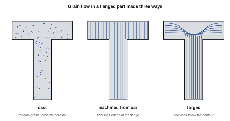
Why are forgings stronger? A cast part has a random grain structure and may hold porosity; a part machined from bar cuts straight through the bar's grain flow, the fibrous alignment of inclusions and grains produced by rolling. A forging bends that grain flow to follow the part's contour. In a forged gear blank, the flow lines run around the rim and into the tooth roots, so a fatigue crack must cut across them instead of running along them. Forging also closes internal voids and refines the grain. The result is higher fatigue strength and toughness, especially in the directions that matter.
For an open-die upsetting operation, compressing a cylinder between flat dies, the ideal force is the flow stress times the current area. Friction at the die faces resists the outward flow of metal and makes the cylinder barrel, raising the force. A common correction for a cylinder of diameter \(D\) and height \(h\) is a shape factor that grows with \(D/h\) and with the friction coefficient.
The force is greatest at the end of the stroke, when the area is largest, the height smallest and the metal most strain hardened. Closed-die forging needs considerably more force than open-die forging of the same plan area, because the flash land deliberately restricts outflow to force metal into the die corners; multiplying the flow stress by the area including flash and a factor of about 6 to 10 is a common first estimate for complex parts.
Worked problem
Press force for upsetting a gear blank
A 4140 steel billet 60 mm (2.36 in) in diameter and 90 mm (3.54 in) long is hot upset at 1150 °C (2100 °F) to a height of 35 mm (1.38 in) before closed-die forging. At this temperature and the press's strain rate the flow stress is about 90 MPa (13 ksi), and the friction coefficient is 0.3. Estimate the force at the end of upsetting.
Show solution
- Volume \(V = \pi(30)^2(90) = 254\,500\ \text{mm}^3\). Final area \(A = V/h = 254\,500/35 = 7270\ \text{mm}^2\), so \(D = 96.2\ \text{mm}\).
- Shape factor \(K_f = 1 + 0.4(0.3)(96.2)/35 = 1.33\).
- Force \(F = 1.33(90)(7270) = 8.70 \times 10^5\ \text{N} \approx 0.87\ \text{MN}\), about 89 metric tons-force.
Answer: Upsetting needs under 1 MN (about 98 US tons), but the closed-die finishing blow, with its flash, will need several times more. The forge supplier plans to use a 16 MN (1800 US ton) mechanical press.
# Bulk forming estimates for KG-40 parts
import math

# 1. Cold rolling a strip in one pass
K, n = 530.0, 0.26            # MPa, strain-hardening law for annealed low-carbon steel
w, h0, hf, R, N = 300.0, 25.0, 22.0, 250.0, 50    # mm, mm, mm, mm, rpm
L = math.sqrt(R * (h0 - hf))                     # projected contact length, mm
eps = math.log(h0 / hf)
sig_avg = K * eps ** n / (1 + n)                 # average flow stress, MPa
F = sig_avg * w * L                              # N
P = 2 * math.pi * N * F * (L / 1000) / 60        # W, both rolls
print(f"Rolling: L = {L:.1f} mm, strain = {eps:.3f}, mean flow stress = {sig_avg:.0f} MPa")
print(f"         force = {F/1e6:.2f} MN, power = {P/1000:.0f} kW")

# 2. Hot upsetting a 4140 billet: force through the stroke
D0, H0 = 60.0, 90.0
V = math.pi * D0 ** 2 / 4 * H0
sigma_f, mu = 90.0, 0.3       # MPa (hot, roughly constant), friction coefficient
print("\nUpsetting:  h (mm)   D (mm)   K_f    force (MN)")
for h in (90, 75, 60, 45, 35):
    A = V / h
    D = math.sqrt(4 * A / math.pi)
    Kf = 1 + 0.4 * mu * D / h
    print(f"           {h:6.0f}   {D:6.1f}   {Kf:4.2f}   {Kf * sigma_f * A / 1e6:8.3f}")

# 3. Hot extrusion pressure (Johnson formula) for an aluminum section
sig_ext, a, b = 45.0, 0.8, 1.4   # MPa at about 480 C; empirical constants
billet_area = math.pi * 175 ** 2 / 4   # 175 mm billet
print("\nExtrusion:  ratio   pressure (MPa)   ram force (MN)")
for rx in (10, 20, 40, 60):
    p = sig_ext * (a + b * math.log(rx))
print(f" {rx:5d} {p:14.0f} {p * billet_area / 1e6:14.1f}")Rolling: L = 27.4 mm, strain = 0.128, mean flow stress = 246 MPa
force = 2.02 MN, power = 290 kW
Upsetting: h (mm) D (mm) K_f force (MN)
90 60.0 1.08 0.275
75 65.7 1.11 0.337
60 73.5 1.15 0.438
45 84.9 1.23 0.624
35 96.2 1.33 0.870
Extrusion: ratio pressure (MPa) ram force (MN)
10 181 4.4
20 225 5.4
40 268 6.5
60 294 7.1Extrusion and drawing
Extrusion pushes a billet through a die opening, like toothpaste from a tube, producing long parts of constant cross-section. Aluminum window frames, heat sinks, rails for linear guides and many tube sections are extruded. In direct extrusion, the ram pushes the billet through a stationary die and the billet slides against the container walls, so friction adds to the force. In indirect extrusion, the die is mounted on a hollow ram and moves into the billet, which does not slide, so the force is lower. Hot extrusion of aluminum at around 450 to 500 °C is routine; cold extrusion, often called impact extrusion, makes cans, battery cases and short steel parts such as gear blanks and bolts.
The extrusion ratio \(r_x = A_0/A_f\) measures the reduction. A widely used empirical formula, due to Johnson, estimates the extrusion pressure from the ideal strain \(\ln r_x\) with constants that account for redundant work and friction.
Drawing is the reverse arrangement: the metal is pulled through a die rather than pushed. Wire and tube drawing reduce diameter in a series of dies, each giving a modest reduction, because the drawn material must carry the pulling stress without yielding. In practice a single pass rarely exceeds about 30 to 45 percent area reduction. Bar drawing produces the cold-drawn steel bar with a bright, accurate surface that Kestrel Drive Systems uses for shafts that need little machining.
Forming defects and how to avoid them
Each process has characteristic defects. In rolling, edges can crack when the metal's ductility is low, and too much reduction can split the center of a thick plate. In forging, laps form when a fold of metal is pressed over another surface without welding, leaving a crack-like seam; good die design and preform shapes prevent them. Cold shuts in forgings arise similarly when two flowing fronts meet without fusing. Underfill leaves die corners empty when the billet is too small or the flash too free. In extrusion, a central burst or chevron crack can form inside the product when the die angle and reduction are badly matched, and surface cracking appears when the temperature or speed is too high. Many of these defects are hidden below the surface, so critical forgings are inspected by ultrasonic or magnetic particle methods.
Equipment and safety
Forging hammers deliver energy in a blow; mechanical presses deliver a fixed stroke at high speed; hydraulic presses deliver a set force slowly and are preferred for large or slow-forming parts. Rolling mills range from small laboratory stands to hot strip mills a kilometer long. All of them store enormous energy, and their hazards are crushing, ejected scale and hot metal, noise from hammers and burns from billets at forging heat. Presses must be guarded and interlocked, operators kept out of the die space with tongs and manipulators, and hearing protection worn near hammers.
Common mistakes
MistakeUsing engineering strain for large forming strains.
InsteadUse true strain, ε = ln(h₀/h) or ln(A₀/A).
MistakeUsing the final flow stress for the whole operation's energy.
InsteadAverage the flow stress over the strain: σ̄ = Kεⁿ/(1+n) for power-law hardening.
MistakeEstimating forging force at the start of the stroke.
InsteadThe force peaks at the end, with the largest area, smallest height and highest flow stress.
MistakeIgnoring friction in upsetting.
InsteadMultiply by a shape factor such as 1 + 0.4μD/h; friction can raise the force substantially.
MistakeAssuming hot-worked parts are strain hardened.
InsteadRecrystallization during hot working removes strain hardening; only cold work raises strength this way.
Summary and key terms
- Bulk forming shapes solid metal by plastic flow; true strain and average flow stress are used for force estimates.
- Cold work gives accuracy and strength but needs high force; hot work gives low flow stress and large shape changes.
- Rolling: contact length L = √(R d), force ≈ σ̄ w L, maximum draft about μ²R.
- Forging aligns grain flow with the part contour, raising fatigue strength; force peaks at the end of the stroke.
- Upsetting force F = (1 + 0.4μD/h) σ_f A; closed-die forging with flash needs several times more.
- Extrusion pressure p ≈ σ̄(a + b ln r_x); drawing reductions per pass are limited by the strength of the drawn product.
- Flow stress
- The true stress needed to keep a metal deforming plastically at a given strain and strain rate.
- Hot working
- Deformation above the recrystallization temperature, so the metal does not strain harden.
- Draft
- In rolling, the reduction in thickness in one pass, h₀ − h_f.
- Neutral point
- The point in the roll gap where strip speed equals roll surface speed.
- Open-die forging
- Forging between flat or simple dies that do not enclose the work.
- Impression-die forging
- Forging in shaped dies that the metal fills; excess escapes as flash.
- Flash
- Excess metal squeezed out between forging dies and trimmed off.
- Grain flow
- The fibrous alignment of grains and inclusions produced by working the metal.
- Extrusion ratio
- The ratio of billet cross-sectional area to product area.
- Lap
- A forging defect where metal folds over itself without bonding.
Practice problems
Work each problem on paper first, then reveal the answer to check.
Find the contact length for a 4 mm draft with 300 mm radius rolls.
Show answer
L = √(300 × 4) = 34.6 mm.
For K = 600 MPa and n = 0.2, find the average flow stress for a true strain of 0.3.
Show answer
σ̄ = 600(0.3)^0.2/1.2 = 393 MPa.
A cylinder 50 mm high is upset to 20 mm. Find the true strain.
Show answer
ε = ln(50/20) = 0.92.
Why are forged gears preferred over gears machined from bar for highly loaded drives?
Show answer
Forging aligns grain flow with the tooth contours and closes voids, raising fatigue strength and toughness.
A round bar 40 mm in diameter is extruded to 20 mm. Find the extrusion ratio and ideal strain.
Show answer
r_x = 4; ln 4 = 1.39.
In the program, change the friction coefficient to 0.5. What is the new final upsetting force?
Show answer
K_f rises to 1.55 and F to about 1.01 MN.
Lesson quiz · 5 questions
Score 60% or more to complete this lesson.
Create a free account to save your progress, take quizzes and earn a certificate.