
MEC-280 · Lesson 10 of 12 · 22 min
Processing plastics and composites
Not everything on the KG-40 is metal. Its breather body and dipstick handle are injection molded glass-filled nylon, its oil seals are molded nitrile rubber, its wiring is sheathed in extruded PVC, and a lightweight guard over the input coupling is compression molded sheet molding compound, a glass-fiber-reinforced polyester. Polymers now outweigh metals in many products by volume, and their processes are fast, energy-efficient and capable of complex shapes in one step. This lesson covers how thermoplastics and thermosets are processed, with injection molding in detail, and then the main processes for fiber-reinforced composites. Amira, who studied polymers in MEC-250, works with the molding supplier on the breather body.
Thermoplastics, thermosets and how they flow
Recall from MEC-250 that thermoplastics, such as polyethylene, polypropylene, nylon and polycarbonate, soften when heated and harden when cooled, reversibly, because their long chains are not chemically linked to each other. They are processed as melts and can be reground and remolded. Thermosets, such as epoxies, phenolics, polyester resins and vulcanized rubbers, start as liquids or soft compounds and cure by a chemical reaction that crosslinks the chains into a network; once cured, they cannot be remelted. Their processes must shape the material before or while it cures.
Polymer melts are extremely viscous, thousands to millions of times more viscous than water, and their viscosity drops sharply as shear rate rises, a behavior called shear thinning. A melt that barely moves under gravity flows readily when forced through a narrow gate at high speed. Viscosity also falls with temperature, but processing temperatures are limited by thermal degradation. Molders adjust melt temperature, injection speed and pressure to fill thin sections before the melt freezes. Many polymers, especially nylons and polyesters, absorb moisture and must be dried before processing, or the water turns to steam in the melt and breaks down the chains, leaving brittle parts with splay marks.
Extrusion
Extrusion is the highest-volume polymer process. A rotating screw inside a heated barrel conveys plastic pellets forward, melts them by friction and conducted heat, pressurizes the melt and pushes it through a shaped die. The emerging profile is cooled by water or air and pulled away at a steady speed. Extrusion makes pipe, tubing, window profiles, wire insulation, sheet and film. Blown film extrusion inflates a thin tube of melt into a large bubble to make plastic bags and packaging film. Co-extrusion combines several layers, for example a barrier layer between structural layers in food packaging.
Extrudates swell as they leave the die, because the stretched chains recover partly when the confining pressure is removed; this die swell must be allowed for in die design. Profiles with uneven walls cool unevenly and warp, so profile designers keep walls uniform, just as casting designers do.
Injection molding
Injection molding makes most plastic parts: housings, caps, gears, clips, connectors, medical devices, toys. A reciprocating screw melts and accumulates a measured shot of plastic at the front of the barrel, then moves forward like a plunger to inject it into a closed steel mold at high pressure, often 50 to 150 MPa at the nozzle. The screw holds pressure while the part begins to cool, packing in extra melt to compensate for shrinkage, then rotates to prepare the next shot while the part cools in the mold. The mold opens, ejector pins push the part out, and the cycle repeats, typically in 15 to 60 seconds.
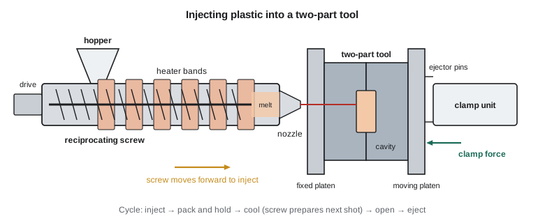
The mold itself is a precision tool. Melt flows from the nozzle through a sprue, along runners and through gates into one or more cavities. Hot runner systems keep the runners molten so that no runner scrap is produced. Cooling channels drilled through the mold carry water to remove heat; cooling is usually the longest part of the cycle. Ejector pins, slides for side features and lifters for undercuts add complexity and cost. A simple single-cavity mold may cost 10 000 to 30 000 dollars; a complex multi-cavity mold for high volume can cost several hundred thousand. The breather body mold has two cavities and a hot runner.
The clamp must hold the mold shut against the cavity pressure acting on the part's projected area in the direction of opening. If the clamp is too weak, the mold parts slightly and melt squeezes out as flash.
The cooling time is governed by heat conduction through the wall, and so it rises with the square of wall thickness. For a plate-like wall of thickness \(s\) and thermal diffusivity \(\alpha\), cooling from melt temperature \(T_m\) to an ejection temperature \(T_e\) with the mold at \(T_w\), a standard estimate is:
This square law is why molded parts are designed with thin, uniform walls, typically 1 to 4 mm, with ribs for stiffness instead of thick sections. Doubling a wall from 2 to 4 mm roughly quadruples the cooling time and cost per part, and thick sections also sink and form voids as their cores shrink.
Worked problem
Clamp force and cooling time for the breather body
The breather body in 30 % glass-filled nylon 6 has a projected area of 2600 mm² (4.03 in²) per cavity, two cavities, and a nominal wall of 2.5 mm (0.098 in). The supplier estimates an average cavity pressure of 45 MPa (6500 psi). Melt temperature is 280 °C, mold temperature 85 °C and ejection temperature 160 °C, with thermal diffusivity \(1.2 \times 10^{-7}\ \text{m}^2/\text{s}\). Find the clamp force and the cooling time.
Show solution
- Clamp force \(= 45(2600)(2) = 234\,000\ \text{N} = 234\ \text{kN}\).
- Temperature ratio \(= (280 - 85)/(160 - 85) = 2.60\); log term \(= \ln(1.273 \times 2.60) = \ln 3.31 = 1.197\).
- Cooling time \(t_c = (0.0025)^2/(\pi^2 \times 1.2 \times 10^{-7}) \times 1.197 = 5.28 \times 1.197 = 6.3\ \text{s}\).
- With injection, packing, mold opening and ejection, the total cycle is about 20 s.
Answer: About 234 kN (26 US tons), so a 55-ton machine gives a safe margin, and a cooling time of about 6 s. At 20 s per cycle and two parts per cycle, one machine makes 360 parts per hour.
# Injection molding estimates for the KG-40 breather body (30 % glass-filled nylon 6)
import math

p_cav, A_proj, cavities = 45.0, 2600.0, 2          # MPa, mm^2 per cavity
F = p_cav * A_proj * cavities                       # N
print(f"Clamp force: {F/1000:.0f} kN; with a 1.5 safety factor choose at least {1.5*F/1000:.0f} kN")

alpha = 1.2e-7                                      # thermal diffusivity, m^2/s
Tm, Tw, Te = 280.0, 85.0, 160.0                     # melt, mold, ejection temperatures (C)

def t_cool(s_mm):
    s = s_mm / 1000
    return s ** 2 / (math.pi ** 2 * alpha) * math.log(4 / math.pi * (Tm - Tw) / (Te - Tw))

print("\nWall (mm)  cooling time (s)")
for s in (1.5, 2.0, 2.5, 3.0, 3.5, 4.0):
    print(f"{s:9.1f}  {t_cool(s):16.1f}")

# Cycle time and part cost
t_inject, t_open_eject = 2.5, 6.0                   # s
t_hold = 5.0
cycle = t_inject + t_hold + t_cool(2.5) + t_open_eject
rate = 60.0                                         # machine and operator, dollars per hour
mold_cost, volume = 48000.0, 3000 * 2 * 5          # two breathers per gearbox, five years
mass, resin = 0.042, 6.50                           # kg per part, dollars per kg
parts_per_hour = 3600 / cycle * cavities
cost = rate / parts_per_hour + mass * resin * 1.04 + mold_cost / volume   # 4 % scrap and regrind loss
print(f"\nCycle {cycle:.1f} s, {parts_per_hour:.0f} parts per hour, cost {cost:.2f} dollars per part")

# Wall that doubles the 2.5 mm cooling time
s_double = 2.5 * math.sqrt(2)
print(f"Cooling time doubles at a wall of {s_double:.2f} mm")Clamp force: 234 kN; with a 1.5 safety factor choose at least 351 kN
Wall (mm) cooling time (s)
1.5 2.3
2.0 4.0
2.5 6.3
3.0 9.1
3.5 12.4
4.0 16.2
Cycle 19.8 s, 363 parts per hour, cost 2.05 dollars per part
Cooling time doubles at a wall of 3.54 mmDesigning molded parts
Good molded part design follows a short list. Keep walls uniform and as thin as function allows. Add ribs to stiffen, with rib thickness about half to two thirds of the wall they join, to avoid sink marks on the opposite face. Give every surface draft, usually 0.5 to 2 degrees, so the part releases from the mold. Use generous radii at corners, at least half the wall thickness inside, to help flow and reduce stress concentration. Avoid undercuts that need slides, or design snap fits so they can be released by simple mold actions. Locate gates where the weld lines, formed where two melt fronts meet, will not weaken a highly stressed area, and remember that glass fibers align with the flow, making the part stronger along the flow than across it.
Shrinkage is not uniform: unfilled polypropylene shrinks around 1.5 to 2 percent, glass-filled nylon only about 0.3 to 0.6 percent along the flow but more across it. Differential shrinkage causes warpage. Mold flow simulation predicts filling, weld lines, fiber orientation, shrinkage and warpage before the mold is cut, and molders tune the process with design of experiments on the first trial shots.
Other polymer processes
Blow molding makes hollow parts such as bottles and fuel tanks by inflating a tube or preform of hot plastic against a cold mold. Thermoforming heats a plastic sheet and draws it over a mold by vacuum or pressure, making trays, enclosures and machine covers with inexpensive tooling. Rotational molding tumbles powder in a heated mold to make large hollow parts like tanks and kayaks. Compression molding places a charge of thermoset compound in a heated open mold that closes to shape and cure it; rubber seals and the KG-40 coupling guard are compression molded. Reaction injection molding mixes two liquid components that react in the mold, suiting large polyurethane parts.
Fiber-reinforced composites
As MEC-250 showed, fibers of glass, carbon or aramid in a polymer matrix give very high strength and stiffness for their weight. Processing a composite means placing fibers in the right directions, wetting them with resin, consolidating out the air and curing. Hand lay-up and spray-up place glass mat and resin on an open mold; they are cheap and suit boat hulls and large covers but are labor intensive and release styrene vapor. Vacuum bagging and resin infusion use a sealed bag and vacuum to compact the laminate and draw in resin, improving fiber content and reducing emissions. Prepreg laminates, fiber sheets already impregnated with partly cured resin, are laid up precisely and cured under heat and pressure in an autoclave; aircraft structures and high-performance parts are made this way.
For volume production, resin transfer molding injects resin into dry fiber preforms in a closed mold. Sheet molding compound, chopped glass fiber in a thickened polyester paste, is compression molded in steel tools in a few minutes and is used for truck panels, electrical enclosures and the KG-40 guard. Filament winding wraps resin-wetted fibers around a rotating mandrel to make pipes, pressure vessels and drive shafts like the carbon-epoxy sprayer shaft in MEC-250. Pultrusion pulls fiber bundles through a resin bath and a heated die to make constant-section profiles such as ladder rails and gratings.
Composite defects include voids, dry spots where resin did not reach, wrinkles in fiber layers, delaminations between plies and incorrect fiber orientation. Inspection by ultrasound, tap testing and, for critical parts, X-ray computed tomography finds them. Machining composites wears tools quickly and produces hazardous dust, so dust extraction and respiratory protection are essential.
Polymer processing and the environment
Thermoplastic scrap, such as runners and rejected parts, can often be reground and blended back into production, within limits that protect properties. Thermosets and most composites cannot be remelted, which makes them hard to recycle; mechanical grinding into filler, pyrolysis to recover fibers and newer recyclable resin systems are all in use or under development. Extended producer responsibility rules in many provinces and states are pushing designers to choose recyclable materials, mark resin types and avoid mixing incompatible polymers in one part.
Common mistakes
MistakeMolding hygroscopic resins like nylon without drying.
InsteadDry to the supplier's moisture limit; wet nylon degrades and gives brittle parts.
MistakeDesigning thick sections in molded parts.
InsteadCooling time scales with wall thickness squared; thick sections also sink and void.
MistakeChoosing a press from the part's total area instead of its projected area.
InsteadClamp force depends on projected area in the opening direction times cavity pressure.
MistakeAssuming glass-filled plastic parts are equally strong in all directions.
InsteadFibers align with flow; strength across the flow and at weld lines is lower.
MistakeTreating thermosets as recyclable like thermoplastics.
InsteadCured thermosets cannot be remelted; plan end-of-life handling at the design stage.
Summary and key terms
- Thermoplastics melt and resolidify reversibly; thermosets cure irreversibly; melts are viscous and shear thinning.
- Extrusion makes continuous profiles, pipe, film and sheet; die swell and uniform walls matter.
- Injection molding injects melt into steel molds; clamp force = cavity pressure × projected area.
- Cooling time grows with wall thickness squared, so molded parts use thin, uniform walls with ribs.
- Blow molding, thermoforming, rotational molding and compression molding suit hollow, sheet, large or thermoset parts.
- Composites are made by lay-up, infusion, prepreg and autoclave, RTM, SMC, filament winding and pultrusion.
- Shear thinning
- A fall in viscosity as shear rate increases.
- Die swell
- The expansion of an extrudate as it leaves the die.
- Injection molding
- Injecting molten plastic under pressure into a closed mold.
- Hot runner
- A heated runner system that keeps melt molten between shots.
- Packing
- Holding injection pressure to add melt as the part shrinks.
- Clamp force
- The force holding a mold closed against cavity pressure.
- Weld line
- A line where two melt fronts meet, often weaker than the surrounding material.
- Sink mark
- A depression on a surface opposite a thick section, caused by shrinkage.
- Prepreg
- Fiber reinforcement pre-impregnated with partly cured resin.
- Resin transfer molding
- Injecting resin into dry fiber preforms in a closed mold.
- Pultrusion
- Pulling resin-wetted fibers through a heated die to make constant profiles.
Practice problems
Work each problem on paper first, then reveal the answer to check.
A part with 5000 mm² projected area is molded at 40 MPa cavity pressure in a four-cavity mold. Find the clamp force.
Show answer
F = 40 × 5000 × 4 = 800 kN.
If the wall of a part increases from 2 mm to 3 mm, by roughly what factor does cooling time rise?
Show answer
(3/2)² = 2.25.
Why are ribs made thinner than the wall they join?
Show answer
To avoid a thick junction that would cause sink marks and voids.
Which process makes plastic fuel tanks?
Show answer
Blow molding.
Name a composite process suited to pipes and pressure vessels.
Show answer
Filament winding.
In the program, what wall thickness doubles the 2.5 mm cooling time?
Show answer
About 3.5 mm.
Lesson quiz · 5 questions
Score 60% or more to complete this lesson.
Create a free account to save your progress, take quizzes and earn a certificate.