
MEC-280 · Lesson 4 of 12 · 23 min
Sheet metal forming
The KG-40 gearbox bolts to the tractor through a sheet steel guard and a pair of formed mounting brackets, and its breather sits under a deep-drawn steel cap. None of these parts is glamorous, but sheet metal parts are everywhere in machines: enclosures, brackets, panels, car bodies, appliance cases, ducts, cans and aircraft skins. Sheet forming is fast, uses relatively cheap material and produces light, stiff parts. This lesson covers cutting sheet, bending it, drawing it into cups, and the presses and dies that do the work. Carla Brandt runs Kestrel Drive Systems's small press shop, and the bracket design gives her and Amira a chance to work through each step.
Sheet metal is usually defined as material less than about 6 mm thick; thicker material is plate. Low-carbon steel, often with a zinc coating, is the most common sheet; aluminum alloys, stainless steels and copper alloys follow. Because sheet is thin, it is formed mainly by bending and stretching rather than by squeezing, and the forces are modest compared with bulk forming. The main concerns are different too: cracking where the sheet stretches too far, wrinkling where it is compressed, and springback when the load is removed.
Shearing, blanking and punching
Most sheet parts start as a flat shape cut from a coil or sheet. Shearing cuts along a straight line between two blades. Blanking cuts a closed outline with a punch and die, and the piece that falls through is the part, called the blank. Punching, or piercing, uses the same tooling but the piece that falls out is scrap and the sheet with the hole is the part. Other cutting operations include notching, trimming, slotting and lancing, which cuts and bends a tab in one step.
A sheared edge is not a clean cut. As the punch descends, it first deforms the sheet plastically, rounding the top edge into a rollover zone. It then shears the metal, leaving a smooth, burnished band. Finally the remaining material fractures, leaving a rough, angled fracture zone and a small burr on the far side. The clearance between punch and die controls the balance. Too little clearance makes secondary shearing and high force; too much leaves a large burr and a rough edge. Typical clearance is 4 to 8 percent of sheet thickness per side for steel, more for hard materials and less for soft ones.
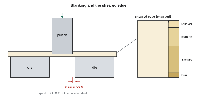
The force needed to blank or punch is the shear strength of the sheet multiplied by the area being sheared, which is the length of the cut outline times the thickness. Shear strength is about 0.7 to 0.8 of the ultimate tensile strength for most sheet metals.
Because all of the cut happens at once with a flat punch, blanking forces can be large. Grinding a shear angle on the punch, so that it enters the sheet progressively, spreads the cut over more of the stroke and lowers the peak force, much like scissors cut with less effort than a guillotine. Fine blanking uses very small clearance, a V-ring that clamps the sheet and a counter-punch that supports the blank, to produce a fully burnished, square edge that needs no machining; small gears and seat-adjuster parts are fine blanked.
Bending
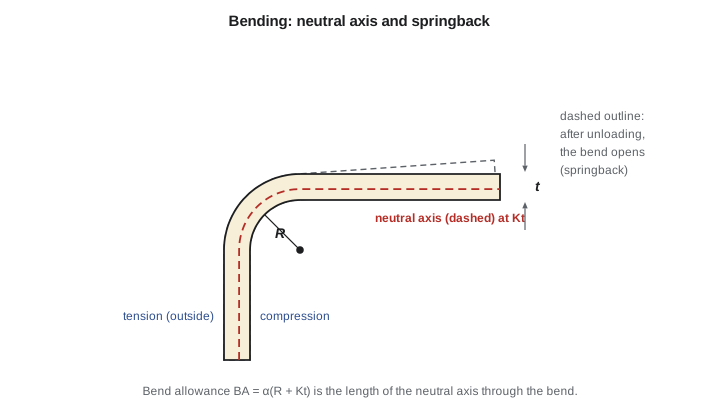
Bending strains the sheet across its thickness. The outer fibers stretch, the inner fibers compress and, somewhere near the middle, a neutral axis has no strain. For a bend of inside radius \(R\) in a sheet of thickness \(t\), the neutral axis sits slightly inside the mid-thickness for tight bends, at a distance \(K t\) from the inside surface, where \(K\) is the K-factor, about 0.33 for very tight bends and 0.5 for generous ones. To find the length of flat sheet needed for a bent part, designers add straight lengths to the length of the neutral axis around each bend, called the bend allowance.
The outer surface of the bend carries the largest tensile strain, about \(1/(1 + 2R/t)\) in engineering terms. If that strain exceeds the material's ductility, the outside of the bend cracks. Each material therefore has a minimum bend radius, usually expressed as a multiple of thickness: about 0.5t for soft low-carbon steel, 1t to 2t for harder steels and up to 4t or more for hard aluminum tempers. Bending across the rolling direction is more forgiving than bending parallel to it, because inclusions and grains elongated by rolling open more easily when pulled crosswise.
When the bending load is removed, the elastic part of the strain recovers and the bend opens slightly. This springback is larger for high-strength materials, thin sheet and large radii, because a greater share of the deformation is elastic. A common approximation relates the radius before and after release to the ratio of yield stress to elastic modulus.
Press brake operators compensate for springback by overbending, bending past the target angle so that the part springs back to it, or by bottoming and coining, squeezing the bend region in the die so that it yields through the thickness. Modern CNC press brakes measure the angle during the stroke and correct automatically.
Worked problem
Flat length and springback for the mounting bracket
The KG-40 mounting bracket is an L-shape bent 90° from 4.0 mm (0.157 in) hot-rolled steel with \(Y = 300\ \text{MPa}\) (43.5 ksi), \(E = 205\ \text{GPa}\). The two legs measure 80 mm and 60 mm to the outside of the bend, the inside radius is 6 mm and K = 0.42. Find the flat blank length and the springback in angle.
Show solution
- Straight lengths: each leg minus the outside setback, \(R + t = 10\ \text{mm}\): 70 mm and 50 mm.
- Bend allowance: \(BA = (\pi/2)(6 + 0.42 \times 4) = 12.06\ \text{mm}\). Flat length \(= 70 + 50 + 12.06 = 132.1\ \text{mm}\).
- Springback: \(R_i Y/(E t) = 6(300)/(205\,000 \times 4) = 0.00220\), so \(R_i/R_f \approx 1 - 3(0.00220) = 0.99341\) and \(R_f = 6.04\ \text{mm}\).
- The bent length of the neutral axis is unchanged, so the angle after release is \(90°(6 + 1.68)/(6.04 + 1.68) = 89.5°\).
Answer: A blank of 132 mm and a bend of about half a degree past 90° gives the right part. With a high-strength steel of three times the yield stress, the springback would roughly triple, which is why such steels need careful die compensation.
# Sheet metal calculations for the KG-40 bracket and breather cap
import math

# 1. Blanking the bracket outline from 4.0 mm steel
t, Su = 4.0, 420.0                 # mm, MPa
Ss = 0.7 * Su
perimeter = 2 * (132.1 + 50.0) + 4 * math.pi * 11.0 / 2   # mm: rectangle with two 11 mm holes
F_blank = Ss * t * perimeter
print(f"Blanking: perimeter {perimeter:.0f} mm, force {F_blank/1000:.0f} kN")

# 2. Flat length of the L-bracket
legs, R, K, angle = (80.0, 60.0), 6.0, 0.42, math.radians(90)
setback = R + t                    # outside setback for a 90 degree bend
BA = angle * (R + K * t)
flat = sum(legs) - 2 * setback + BA
print(f"Bend allowance {BA:.2f} mm, flat length {flat:.1f} mm")

# 3. Springback for three steels (same bracket)
E = 205000.0
print("\nSteel             Y (MPa)   R_f (mm)   angle after release (deg)")
for name, Y in (("hot-rolled", 300.0), ("HSLA 550", 550.0), ("AHSS 980", 900.0)):
    x = R * Y / (E * t)
    Rf = R / (4 * x ** 3 - 3 * x + 1)
    after = 90.0 * (R + K * t) / (Rf + K * t)
    print(f"{name:16s} {Y:7.0f}   {Rf:8.3f}   {after:8.2f}")

# 4. Breather cap: blank size, drawing ratio and punch force
Dp, h, tc, Su_c = 50.0, 30.0, 1.0, 330.0   # mm, mm, mm, MPa (drawing-quality steel)
for depth in (h, 45.0):
    Db = math.sqrt(Dp ** 2 + 4 * Dp * depth)
    ratio = Db / Dp
    F = math.pi * Dp * tc * Su_c * (ratio - 0.7)
    verdict = "one draw" if ratio <= 2.0 else "near or over the limit: plan a redraw"
    print(f"Cap depth {depth:.0f} mm: blank {Db:.1f} mm, ratio {ratio:.2f}, "
f"punch force {F/1000:.1f} kN ({verdict})")Blanking: perimeter 433 mm, force 510 kN Bend allowance 12.06 mm, flat length 132.1 mm Steel Y (MPa) R_f (mm) angle after release (deg) hot-rolled 300 6.040 89.54 HSLA 550 550 6.073 89.15 AHSS 980 900 6.121 88.60 Cap depth 30 mm: blank 92.2 mm, ratio 1.84, punch force 59.3 kN (one draw) Cap depth 45 mm: blank 107.2 mm, ratio 2.14, punch force 74.9 kN (near or over the limit: plan a redraw)
Deep drawing
Deep drawing makes cup-shaped and box-shaped parts from flat blanks: beverage cans, sinks, cooking pots, oil filter shells and the KG-40 breather cap. A punch pushes the center of a blank into a die, and the outer part of the blank, the flange, is pulled inward over the die radius to form the cup wall. As the flange moves inward, its circumference shrinks, so it is compressed in the hoop direction and tends to wrinkle. A blank holder presses on the flange to prevent wrinkles, but if it presses too hard, friction stops the flange from flowing and the cup wall tears near the punch radius.
The severity of a draw is measured by the drawing ratio, the blank diameter divided by the punch diameter, \(D_b/D_p\). For a single draw of a cylindrical cup, the limiting drawing ratio for most sheet steels is about 1.8 to 2.2; above it, the wall fails before the flange can be drawn in. Deeper cups are made by redrawing in stages, often with annealing between stages. Materials with a high normal anisotropy \(\bar r\), meaning they resist thinning through the thickness more than they resist deforming in the plane, draw better. The blank diameter for a simple cup follows from equating surface areas, since sheet thickness changes little overall.
The breather cap is 50 mm in diameter and 30 mm deep. Its blank diameter is \(\sqrt{50^2 + 4(50)(30)} = 92.2\ \text{mm}\), a drawing ratio of 1.84. That is within the limit for drawing-quality steel, so the cap can be made in a single draw, with the program in this lesson confirming the punch force.
Stretch forming, spinning and hydroforming
Several processes make shapes that a simple punch and die cannot. Stretch forming grips a sheet at both ends and pulls it over a form block, stretching it beyond yield so that springback is almost eliminated; aircraft skins and curved architectural panels are made this way. Spinning clamps a disk against a rotating mandrel and presses it onto the mandrel with a roller, forming bowls, reflectors, cones and tank heads at low tooling cost. Hydroforming uses fluid pressure in place of one die half, either pressing sheet onto a single die or expanding a tube inside a die cavity to form complex hollow parts such as exhaust manifolds and frame rails. Incremental forming moves a CNC-driven stylus over a clamped sheet to build up a shape without dedicated dies, useful for prototypes.
Formability and the forming limit diagram
How far can a sheet be stretched before it fails? It depends on the combination of strains. Stretching equally in two directions, like a balloon, is more severe than stretching in one direction while the sheet narrows in the other. Engineers map this with a forming limit diagram: the major strain on the vertical axis, the minor strain on the horizontal axis, and a curve marking the onset of local necking. Test sheets are printed with a grid of small circles, formed, and the circles measured as they become ellipses. Points below the curve are safe; points on or above it will neck or split. Simulation programs now predict these strains for a new die before any steel is cut, and the press shop checks first-off parts with circle grids or optical strain measurement.
Presses, dies and production
Sheet parts are made on mechanical or hydraulic presses rated by their force capacity, from small 200 kN bench presses to car-body presses of 20 MN or more. Simple parts can be made in a single-station die. For high volumes, a progressive die carries a strip through a series of stations, piercing, notching, bending and finally cutting off, one step at each stroke, so a complete part drops off every stroke. Transfer dies move separate blanks between stations with mechanical fingers, which suits larger parts. Turret punch presses and laser or plasma cutters serve low volumes without dedicated dies, and CNC press brakes bend the flat parts they produce. The KG-40 brackets, at 6000 per year, will be laser cut and press-brake bent; a progressive die would only pay off above about 50 000 per year.
Press work is hazardous: a press closing on a hand causes amputation in an instant. Guards, two-hand controls, light curtains and safe stopping distances are required by machine safeguarding rules in both Canada and the United States, and feeding by hand into the die area must be engineered out wherever possible.
Common mistakes
MistakeUsing tensile strength instead of shear strength for blanking force.
InsteadBlanking force is F = S_s t L, with S_s about 0.7 S_u.
MistakeComputing the flat length from the outside dimensions of the bent part.
InsteadAdd straight lengths to the bend allowance measured along the neutral axis.
MistakeSpecifying a bend radius below the material's minimum.
InsteadCheck the minimum bend radius for the material, temper and bend direction relative to rolling.
MistakeIgnoring springback in high-strength sheet.
InsteadSpringback scales with Y/E and R/t; overbend, bottom or coin to compensate.
MistakeDrawing a cup with a blank ratio above the limiting drawing ratio in one step.
InsteadKeep D_b/D_p below about 2, or plan redraws.
Summary and key terms
- Sheet is cut by shearing, blanking and punching; force F = S_s t L and clearance controls edge quality.
- Bending stretches the outside and compresses the inside; the bend allowance BA = α(R + Kt) gives the flat length.
- Each material has a minimum bend radius; springback grows with Y/E and R/t and is offset by overbending or coining.
- Deep drawing pulls a flange into a die; the limiting drawing ratio is about 2 for one draw.
- Stretch forming, spinning, hydroforming and incremental forming make shapes simple dies cannot.
- Forming limit diagrams show safe strain combinations; progressive and transfer dies suit high volume.
- Blanking
- Cutting a closed outline where the removed piece is the part.
- Punching
- Cutting a closed outline where the removed piece is scrap.
- Clearance
- The gap between punch and die cutting edges.
- Burr
- The small ridge left on the far side of a sheared edge.
- Neutral axis
- The surface in a bent sheet that is neither stretched nor compressed.
- Bend allowance
- The length of the neutral axis through a bend.
- K-factor
- The neutral axis position as a fraction of thickness from the inside of a bend.
- Springback
- The partial opening of a bend when the bending load is removed.
- Deep drawing
- Forming a cup or box by pulling a blank into a die with a punch.
- Limiting drawing ratio
- The largest blank-to-punch diameter ratio that can be drawn in one step.
- Progressive die
- A die with several stations that forms a part step by step as a strip advances.
Practice problems
Work each problem on paper first, then reveal the answer to check.
Find the force to punch a 20 mm hole in 3 mm steel with S_u = 450 MPa.
Show answer
F = 0.7(450)(3)(π × 20) = 59.4 kN.
Find the bend allowance for a 90° bend, R = 3 mm, t = 2 mm, K = 0.4.
Show answer
BA = (π/2)(3 + 0.8) = 5.97 mm.
Why does a stronger steel spring back more?
Show answer
Springback depends on Y/E; a higher yield stress with the same modulus means more elastic strain to recover.
A cup 80 mm in diameter and 40 mm deep is to be drawn. Find the blank diameter and drawing ratio.
Show answer
D_b = √(6400 + 12 800) = 138.6 mm; ratio 1.73.
What does a progressive die do?
Show answer
It performs several operations at successive stations as a strip advances, producing a part each stroke.
In the program, raise the cap depth to 45 mm. Can it still be drawn in one step?
Show answer
D_b = 107 mm, ratio 2.14: at the upper end of the range for one draw, so a redraw or a better drawing-quality steel is advisable.
Lesson quiz · 5 questions
Score 60% or more to complete this lesson.
Create a free account to save your progress, take quizzes and earn a certificate.