
MEC-280 · Lesson 2 of 12 · 24 min
Metal casting and solidification
The KG-40 housing will be sand cast in gray iron by a foundry in southern Illinois that has supplied Kestrel Drive Systems for years. Before signing off the pattern, Jonah and Amira visit to review the gating, the risers and the cooling simulation. Casting is the oldest way of shaping metal and still one of the most economical for complex shapes: engine blocks, pump bodies, valve housings, turbine blades and machine bases are all cast. In one step it can produce hollow interiors, varying wall thicknesses and integral bosses that would take hours to machine. This lesson covers the main casting processes, what happens when metal freezes, and how foundries design molds that produce sound castings.
The basic steps of casting
Every casting process follows the same outline. A mold is made with a cavity in the shape of the part, slightly larger to allow for shrinkage. Metal is melted, its chemistry adjusted, and it is poured or injected into the cavity through a gating system. The metal solidifies, the casting is removed, and the gates and risers are cut off. The casting is then cleaned, inspected, often heat treated, and machined on its functional surfaces.
A sand mold is made in two halves held in a flask: the top half is the cope and the bottom half is the drag, meeting at the parting line. A pattern, a full-size model of the part made of wood, plastic or metal, is packed in sand to form the cavity and then withdrawn. Internal passages, such as the oil gallery and the main cavity of the KG-40 housing, are formed by cores: shapes of bonded sand placed in the mold that the metal flows around. After the casting cools, the core sand is shaken out, leaving the hollow.
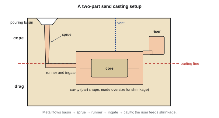
The gating system controls how metal enters. The pouring basin catches the stream; the sprue is a vertical tapered channel that accelerates it; the runner carries it horizontally; and ingates lead it into the cavity. Good gating fills the cavity quickly enough that no section freezes early, but gently enough to avoid turbulence, which folds oxide films and sand into the metal. Filters made of ceramic foam often sit in the runner to trap oxides. Risers are reservoirs of liquid metal attached to the casting; they feed metal into it as it shrinks during solidification, and are cut off afterward.
Expendable-mold processes
Green sand molding uses silica sand bonded with clay and water. It is cheap, reusable after reconditioning and suitable for parts from a few grams to many metric tons. Most iron castings, including the KG-40 housing, are green sand castings. Chemically bonded sands, set with resin binders, give stronger, more accurate molds for larger or more precise parts. Shell molding coats a heated metal pattern with resin-coated sand to form a thin, rigid shell, giving better accuracy and finish at higher tooling cost.
Investment casting, also called the lost-wax process, starts with a wax pattern injected into a metal die. Patterns are assembled onto a wax tree, dipped repeatedly in ceramic slurry and coated with stucco to build a shell. The wax is melted out, the shell is fired, and metal is poured into the hot shell. Investment casting gives excellent detail, thin walls and good tolerances, and it handles alloys too hard to machine easily. Turbine blades, surgical implants, golf club heads and small precision valve parts are investment cast. Lost-foam casting is similar but uses an expanded polystyrene pattern that vaporizes as the metal fills the unbonded sand around it.
Permanent-mold processes
Permanent molds are made of metal and used thousands of times. Gravity permanent-mold casting pours metal into a preheated steel or iron mold; it gives finer grain and better finish than sand, and suits aluminum pistons and wheels. Pressure die casting injects molten metal, usually aluminum, zinc or magnesium, into a hardened steel die at high pressure, often 30 to 100 MPa, and at high speed. Cycle times are tens of seconds, tolerances are tight and walls can be under 2 mm thick. The trade-offs are very expensive dies, limits on part size, and trapped gas porosity that makes many die castings unsuitable for heat treatment or welding.
Low-pressure die casting pushes metal up from a sealed furnace into the die through a fill tube with a modest gas pressure, giving calm filling and sound castings; aluminum car wheels are made this way. Centrifugal casting spins a mold so that metal is flung outward against it, producing dense pipes, cylinder liners and bushings with impurities pushed toward the bore, where they are machined away. Continuous casting, used at steel mills, solidifies metal as it is drawn from a water-cooled mold into an endless strand that is later rolled.
How metal solidifies
A pure metal freezes at a single temperature. If we plot temperature against time as it cools, the curve falls, levels off at the freezing point while latent heat is released, and then falls again once all the metal is solid. Alloys usually freeze over a range of temperatures, between the liquidus and the solidus that we met on phase diagrams in MEC-250. During that range the casting is a mushy mixture of growing solid crystals and remaining liquid.
Solidification starts at the mold wall, where heat is removed fastest. A thin chill zone of fine, randomly oriented grains forms first. Behind it, grains with favorable orientations grow inward as long columnar crystals, parallel to the direction of heat flow. In the center, where the remaining liquid cools more uniformly, equiaxed grains may nucleate. Most alloys grow as dendrites, tree-like crystals whose arms reach into the liquid; the spacing between dendrite arms is smaller when cooling is faster, and finer spacing gives better strength and ductility. Grain refiners, such as titanium-boron additions in aluminum, promote fine equiaxed grains throughout.
Gray cast iron, the KG-40 housing material, solidifies with carbon forming graphite flakes in an iron matrix. The flakes give gray iron its excellent damping and machinability, and they also expand slightly as they form, which partly offsets the shrinkage of the iron. That is one reason gray iron is so easy to cast soundly. Ductile iron, with graphite as spheres instead of flakes, is stronger and tougher but needs magnesium treatment and more careful feeding.
Solidification time and Chvorinov's rule
How long a section takes to freeze depends on how much heat it holds compared with how fast it can lose heat through its surface. Chvorinov's rule captures this with the ratio of volume to surface area, called the casting modulus.
Here \(t_s\) is the solidification time, \(V/A\) is the modulus and \(C_m\) is a mold constant that depends on the metal, the mold material and the pouring temperature; it is found from test castings. A thick, compact section has a large modulus and freezes last; a thin fin or rib freezes first. This is the key to feeding: a riser must freeze after the section it feeds, so its modulus must be larger, typically by 20 percent or more.
Worked problem
Sizing a riser for the housing boss
The heaviest section of the KG-40 housing is a bearing boss that behaves like a block 120 mm × 100 mm × 60 mm, with one 120 × 100 face joined to the rest of the casting (so that face does not cool). Test castings give \(C_m = 2.2\ \text{s/mm}^2\) for this iron and sand. Estimate the boss solidification time and size a cylindrical top riser with height equal to diameter whose modulus is 1.2 times that of the boss.
Show solution
- Volume \(V = 120 \times 100 \times 60 = 720\,000\ \text{mm}^3\). Cooling area excludes the joined face: \(A = 120(100) + 2(120)(60) + 2(100)(60) = 38\,400\ \text{mm}^2\).
- Modulus \(M = 720\,000/38\,400 = 18.75\ \text{mm}\); time \(t_s = 2.2(18.75)^2 = 773\ \text{s} \approx 12.9\ \text{min}\).
- A cylinder with \(H = D\) sitting on the casting loses heat from its side and top only: \(M_r = (\pi D^2 H/4)/(\pi D H + \pi D^2/4) = D/5\).
- Require \(M_r = 1.2(18.75) = 22.5\ \text{mm}\), so \(D = H = 112.5\ \text{mm}\); riser solidification time \(2.2(22.5)^2 = 1114\ \text{s}\).
Answer: A riser about 115 mm in diameter and height feeds the boss and freezes about 5.7 minutes after it. The foundry will confirm the size with a simulation and may use an insulating sleeve to shrink it.
# Solidification times and riser sizing for the KG-40 housing (gray iron, green sand)
Cm = 2.2          # mold constant from test castings, s/mm^2
n = 2

def modulus(V, A):
    return V / A

def t_solid(M):
    return Cm * M ** n

# Housing sections: (volume mm^3, cooling area mm^2); joined faces are left out of the area
sections = {
    "wall 8 mm (per 100 x 100 patch)": (100 * 100 * 8, 2 * 100 * 100),
    "mounting rib 12 x 40": (12 * 40 * 200, 2 * 40 * 200 + 12 * 200),
    "bearing boss 120 x 100 x 60": (120 * 100 * 60, 120 * 100 + 2 * 120 * 60 + 2 * 100 * 60),
}
print("Section                            modulus (mm)   time (s)")
for name, (V, A) in sections.items():
    M = modulus(V, A)
    print(f"{name:34s} {M:10.2f}   {t_solid(M):8.0f}")

# Top riser, cylinder with H = D: modulus = D/5 (side and top cool, base joined)
M_boss = modulus(*sections["bearing boss 120 x 100 x 60"])
factor = 1.2
D = 5 * factor * M_boss
print(f"\nRiser for the boss: D = H = {D:.1f} mm, modulus {D/5:.2f} mm, "
      f"freezes {t_solid(D/5) - t_solid(M_boss):.0f} s after the boss")

# Pattern dimensions with a shrinkage allowance
allowance = {"gray iron": 0.010, "aluminum alloy": 0.013, "steel": 0.020}
part_length = 280.0   # mm, housing length on the drawing
for metal, a in allowance.items():
print(f"Pattern length for {metal:15s}: {part_length * (1 + a):.1f} mm")Section modulus (mm) time (s) wall 8 mm (per 100 x 100 patch) 4.00 35 mounting rib 12 x 40 5.22 60 bearing boss 120 x 100 x 60 18.75 773 Riser for the boss: D = H = 112.5 mm, modulus 22.50 mm, freezes 340 s after the boss Pattern length for gray iron : 282.8 mm Pattern length for aluminum alloy : 283.6 mm Pattern length for steel : 285.6 mm
Shrinkage and the defects it causes
Metals shrink in three stages as they cool from the pouring temperature: liquid contraction as the liquid cools to the liquidus, solidification shrinkage as liquid turns to denser solid, and solid contraction as the solid casting cools to room temperature. Solidification shrinkage is typically 3 to 7 percent by volume for steels and aluminum alloys and much less for gray iron. If liquid cannot reach a freezing region to make up the loss, a shrinkage cavity forms, either a large pipe near the top or scattered microporosity in the last regions to freeze.
Solid contraction does not cause cavities, but it changes dimensions. Patterns are made oversize by a shrinkage allowance, roughly 1 percent for gray iron, 1.3 percent for aluminum alloys and 2 percent for steel, scaled into every dimension. A pattern maker's rule, longer than a normal rule by exactly that allowance, makes the job automatic. Patterns also get a machining allowance on surfaces to be cut and a draft angle, usually 1 to 3 degrees, so the pattern can be drawn from the sand without tearing it.
Feeding works only if solidification is directional: thin regions far from the riser freeze first, and the freezing front advances toward the riser. Foundries arrange this by placing risers on the heaviest sections, by adding chills (metal inserts in the mold that pull heat out fast) to sections that would otherwise freeze late, and by tapering walls so they thicken toward the riser.
| Defect | Appearance | Main cause | Remedy |
|---|---|---|---|
| Shrinkage cavity | Rough-walled void in a heavy section | Poor feeding; isolated hot spot | Larger or better-placed riser, chills, directional solidification |
| Gas porosity | Smooth round holes | Dissolved hydrogen or mold gases | Degassing, drier sand, venting |
| Misrun or cold shut | Incomplete section or unfused seam | Metal too cold or slow; thin walls | Higher pouring temperature, better gating |
| Hot tear | Ragged crack at a corner | Restrained contraction while weak | Generous fillets, collapsible cores |
| Sand inclusion | Embedded sand grains | Mold erosion by turbulent flow | Gentler gating, stronger sand, filters |
| Oxide film | Folded thin skins, often in aluminum | Turbulent filling | Bottom gating, filters, slower fill |
Designing parts for casting
Designers can make a foundry's job far easier. Keep wall thicknesses as uniform as possible, because isolated heavy sections become hot spots that need their own risers. Where thickness must change, change it gradually. Use generous fillets at internal corners, both to avoid hot spots where walls meet and to reduce hot tearing. Avoid large flat areas, which distort, and add ribs to stiffen them. Provide draft on surfaces parallel to the pattern's draw direction, and put the parting line where it is easy to make and where flash can be ground off without harm. Specify machining stock only where needed, and locate datum features on surfaces that the foundry can hold consistently.
Today almost every new casting is simulated before the pattern is made. Software models the filling, the temperature field during solidification and the likely porosity. Jonah's review of the KG-40 simulation found a small hot spot where a mounting boss met the main wall. Adding a 6 mm fillet and a chill on the outside of the boss moved the last-to-freeze region into the riser, and the predicted porosity disappeared.
Safety and the environment in foundries
Foundries combine several serious hazards. Molten metal at 1300 to 1600 °C causes severe burns, and a small amount of water trapped under it can turn to steam and eject metal violently, so ladles, tools and molds must be dry and preheated. Workers wear aluminized clothing, face shields and spats. Silica sand produces respirable crystalline silica dust during shakeout and cleaning, which causes silicosis; dust collection, wet methods and respiratory protection are required, and both Canadian and US exposure limits for respirable silica are strict. Noise, heat stress and lifting heavy ladles add further risks. Environmentally, foundries recycle most of their sand and scrap metal, but they must control emissions from melting and binders.
Common mistakes
MistakeMaking a riser smaller than the section it feeds.
InsteadA riser must freeze after the casting section: its modulus V/A should be at least about 1.2 times that section's modulus.
MistakeIncluding the joined face when computing a section's cooling area.
InsteadOnly surfaces that lose heat to the mold count in A.
MistakeForgetting shrinkage and machining allowances on the pattern.
InsteadScale pattern dimensions by the contraction allowance and add machining stock and draft.
MistakeDesigning sudden changes from thin to thick walls.
InsteadKeep sections uniform or change thickness gradually, with generous fillets.
MistakeAssuming die castings can always be heat treated or welded.
InsteadConventional high-pressure die castings often contain trapped gas that blisters when heated.
Summary and key terms
- Casting fills a cavity with molten metal; the gating system controls filling and risers feed shrinkage.
- Expendable molds (green sand, chemically bonded sand, shell, investment, lost foam) suit complex shapes and low to medium volumes.
- Permanent molds (gravity, high-pressure and low-pressure die casting, centrifugal) suit high volumes and give better finish and tolerance.
- Metals freeze from the mold wall inward as chill, columnar and equiaxed zones, usually by dendritic growth.
- Chvorinov's rule t_s = C_m(V/A)² sets solidification time; risers need a larger modulus than the sections they feed.
- Patterns carry shrinkage allowance, machining stock and draft; uniform walls and fillets prevent hot spots and tears.
- Cope
- The upper half of a sand mold.
- Drag
- The lower half of a sand mold.
- Core
- A shape of bonded sand placed in a mold to form an internal passage.
- Sprue
- The vertical channel that carries metal down from the pouring basin.
- Riser
- A reservoir of liquid metal that feeds a casting as it shrinks.
- Investment casting
- Casting into a ceramic shell built around a wax pattern that is melted out.
- Die casting
- Injecting molten metal into a reusable steel die under pressure.
- Dendrite
- A tree-shaped crystal that grows into the liquid during solidification.
- Casting modulus
- The ratio of a section's volume to its cooling surface area, V/A.
- Chvorinov's rule
- Solidification time is proportional to the square of the casting modulus.
- Shrinkage allowance
- The amount a pattern is made oversize to allow for solid contraction.
- Draft
- A slight taper on pattern surfaces so the pattern can be drawn from the sand.
Practice problems
Work each problem on paper first, then reveal the answer to check.
A cube of side 50 mm cools on all faces. Find its modulus.
Show answer
V/A = 50³/(6 × 50²) = 50/6 = 8.33 mm.
If C_m = 2.2 s/mm², how long does that cube take to solidify?
Show answer
t = 2.2(8.33)² = 153 s.
A sphere and a cube have the same volume. Which freezes faster, and why?
Show answer
The cube: it has more surface area for the same volume, so a smaller modulus.
A gray iron casting must be 400 mm long. With a 1.0 % shrinkage allowance, how long is the pattern?
Show answer
404 mm.
Name the defect: smooth spherical holes near the top of an aluminum casting.
Show answer
Gas porosity, usually from dissolved hydrogen.
In the program, change the riser factor to 1.4. What diameter is needed?
Show answer
D = 5 × 1.4 × 18.75 ≈ 131 mm.
Lesson quiz · 5 questions
Score 60% or more to complete this lesson.
Create a free account to save your progress, take quizzes and earn a certificate.