
MEC-260 · Lesson 9 of 12 · 25 min
GD&T fundamentals: datums, form and orientation
With a proper H7 tolerance on the bore, Owen thought the BB-210 was finished. Marco asked him a question that changed his mind: measured from where? The bore could be exactly 42.010 mm in diameter and still be useless if its axis were tilted a tenth of a degree, or sat 0.3 mm too high, or were not square to the face that locates the bracket against the pump base. Plus-and-minus dimensions control size well, but they are weak at controlling orientation and location, and they never say which surfaces the part is measured from. Geometric dimensioning and tolerancing, universally called GD&T, fills those gaps. This lesson introduces its framework: the feature control frame, datums, and the form and orientation controls. Lesson 10 covers location, profile and runout.
What plus-and-minus tolerancing cannot do
Coordinate tolerancing, with ± values on dimensions, has three weaknesses. It produces square or rectangular tolerance zones for hole positions, which are smaller than the round zone that function usually allows, so good parts are rejected. It does not say which surfaces the measurements start from, so two inspectors who set the part up differently can get different results and both be right. And it says nothing about form and orientation: a flat surface toleranced ± 0.1 mm in thickness can be bowed, a hole can be tilted, and the drawing has no way of saying how much is acceptable except by implication.
GD&T addresses all three. It defines tolerance zones of the shape that function needs, such as a cylinder around a hole axis. It defines datums, the reference features from which measurements are taken, in a specific order that matches how the part is located in assembly. And it provides symbols for each geometric characteristic. In North America the governing standard is ASME Y14.5-2018; internationally it is the ISO GPS system, with ISO 1101 covering geometric tolerancing and ISO 5459 covering datums. The symbols are largely shared, but some rules differ, as noted below.
The fourteen characteristics
ASME Y14.5-2018 defines fourteen geometric characteristics in five categories. Form controls (straightness, flatness, circularity and cylindricity) control the shape of a single feature and never use datums. Orientation controls (parallelism, perpendicularity and angularity) control the tilt of a feature relative to datums. Location is controlled by position, and in the 2018 edition concentricity and symmetry were removed, with position or runout used instead. Profile controls (profile of a line and profile of a surface) can control form, orientation, size and location of irregular surfaces. Runout controls (circular runout and total runout) control the variation of surfaces of revolution about a datum axis. With concentricity and symmetry gone, twelve characteristics remain in current use.
| Category | Characteristic | Datums | Typical use on the bracket |
|---|---|---|---|
| Form | Straightness | Never | Axis of a pin or edge of a long surface |
| Form | Flatness | Never | Mounting face, datum A |
| Form | Circularity | Never | Cross-sections of the bore |
| Form | Cylindricity | Never | Bearing bore surface |
| Orientation | Parallelism | Required | Bore axis to the mounting face |
| Orientation | Perpendicularity | Required | Back locating face to datum A |
| Orientation | Angularity | Required | Grease pad at 30° to datum A |
| Location | Position | Usually | Mounting holes and bore |
| Profile | Profile of a line / surface | Optional | Cast outline of the upright |
| Runout | Circular / total runout | Required | Turned shafts and hubs |
The feature control frame
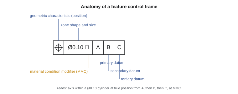
Every geometric tolerance is written in a feature control frame, a rectangle divided into compartments and attached to the feature by a leader or placed with its size dimension. The first compartment holds the characteristic symbol. The second holds the tolerance value, preceded by a diameter symbol if the zone is cylindrical and followed by a material condition modifier if one applies. The remaining compartments name the datums, in order of precedence: primary, secondary and tertiary. The frame is read as a sentence. A frame showing the position symbol, Ø0.10 with the M modifier, then A, B, C, reads: the axis of this feature must lie within a cylindrical zone 0.10 mm in diameter, at maximum material condition, located at the true position defined by basic dimensions from datums A, B and C.
Features of size and Rule #1
GD&T distinguishes between features of size, such as holes, pins, slots and tabs, which have opposed points and a measurable size, and features without size, such as a flat face. For features of size, two limits matter. The maximum material condition (MMC) is the size at which the feature contains the most material: the smallest hole or the largest pin. The least material condition (LMC) is the opposite: the largest hole or the smallest pin. For the 42 H7 bore, MMC is 42.000 mm and LMC is 42.025 mm.
ASME Y14.5 applies Rule #1, the envelope principle, by default: a regular feature of size may not extend beyond a perfect-form boundary at MMC. In other words, if the bore is made at exactly 42.000 mm, its MMC, it must be perfectly round and straight, because any form error would put some point inside the 42.000 mm envelope. As the bore grows toward LMC, form error is allowed up to the difference. Rule #1 therefore controls form automatically through the size tolerance. ISO practice is different: under ISO 8015 the default is the independency principle, in which size and form are independent unless the envelope requirement, an E in a circle, is added to the size tolerance. This is the single most important difference between the two systems, and a drawing that does not name its standard leaves it open.
Datums and the datum reference frame
A datum is a theoretically exact point, axis or plane derived from a real feature on the part, called the datum feature. Datum features are identified on the drawing by a datum feature symbol: a capital letter in a square box attached to the feature with a triangle. Datums are not chosen for convenience in drawing; they should be the features that locate the part in its assembly, because then the tolerances describe how the part functions.
Three mutually perpendicular datum planes form a datum reference frame, a coordinate system fixed to the part. The order of the datums in a feature control frame matters. The primary datum feature contacts its simulator, such as a surface plate, in at least three points and fixes three degrees of freedom: translation perpendicular to the plane and two rotations. The secondary datum feature, perpendicular to the primary, contacts in at least two points and fixes two more. The tertiary datum feature contacts in at least one point and fixes the last. This 3-2-1 scheme removes all six degrees of freedom and makes the inspection setup repeatable.
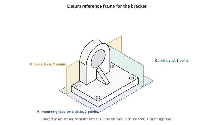
For the BB-210, the bottom mounting face is datum feature A, because it bolts flat to the pump base and sets the bore height and the tilt of the shaft. The machined back face of the base, which sits against a shoulder on the pump base, is datum feature B. The machined right end face, which butts against a stop on the pump base, is datum feature C, which sets the position along the length. Every important feature, the bore, the mounting holes and the grease pad, is related to A, B and C, in that order.
Form tolerances
Form tolerances control the shape of a single feature without reference to datums. Flatness requires all points of a surface to lie between two parallel planes a tolerance apart. Straightness of a line element requires each line on a surface to lie between two parallel lines; straightness of an axis, applied to a feature of size, requires the derived axis to lie within a cylinder. Circularity requires each cross-section of a round feature to lie between two concentric circles. Cylindricity combines circularity, straightness and taper into one zone between two coaxial cylinders.
Under Rule #1, the size tolerance already limits form, so a form tolerance is needed only when the form must be tighter than the size tolerance allows, or when a feature without size, such as a large flat face, needs control. The mounting face of the bracket gets a flatness tolerance of 0.05 mm, which prevents the casting from rocking on the pump base. The bore gets a cylindricity tolerance of 0.01 mm, tighter than Rule #1 would give, because bearing manufacturers recommend tight form for bearing seats so that the outer ring is not distorted.
Worked problem
Evaluating flatness
Marco probes the mounting face at twelve points on a grid and records heights between 7 and 31 µm. The drawing requires flatness 0.05 mm. Is the raw range of 24 µm the flatness?
Show solution
- No. The raw range includes any tilt of the face relative to the measuring machine's table, which flatness does not control; flatness is measured relative to the best plane through the surface itself.
- Fit a plane \(z = a + bx + cy\) to the points by least squares. For Marco's data the plane tilts by about 0.14 µm per mm along the length.
- Subtract the plane from each point. The residuals range from −3.9 to +8.5 µm, so the flatness estimate is about 12.5 µm (the residuals shown are rounded).
- The standard defines flatness using the minimum zone, the narrowest pair of parallel planes; the least-squares estimate is never smaller than the minimum zone, so if it passes, the part passes.
Answer: Flatness is about 12.5 µm, well within 50 µm. The raw range overstated it by half, because it mixed in the tilt of the setup. Separating form from orientation is the first habit of GD&T inspection.
The program repeats Marco's evaluation and a simple orientation check on the bore axis.
# Flatness of the bracket's mounting face (datum A) from a 3 x 4 grid of probe points.
# Heights z are in um relative to an arbitrary zero; x and y in mm.
pts = [
    (10, 10, 12), (43, 10, 15), (77, 10, 19), (110, 10, 22),
    (10, 40, 9),  (43, 40, 21), (77, 40, 16), (110, 40, 20),
    (10, 70, 7),  (43, 70, 10), (77, 70, 14), (110, 70, 31),
]

# Least-squares plane z = a + b x + c y via the 3 x 3 normal equations
n = len(pts)
Sx = sum(p[0] for p in pts); Sy = sum(p[1] for p in pts); Sz = sum(p[2] for p in pts)
Sxx = sum(p[0] ** 2 for p in pts); Syy = sum(p[1] ** 2 for p in pts); Sxy = sum(p[0] * p[1] for p in pts)
Sxz = sum(p[0] * p[2] for p in pts); Syz = sum(p[1] * p[2] for p in pts)
M = [[n, Sx, Sy, Sz], [Sx, Sxx, Sxy, Sxz], [Sy, Sxy, Syy, Syz]]
for i in range(3):                          # Gaussian elimination
    piv = M[i][i]
    M[i] = [v / piv for v in M[i]]
    for r in range(3):
        if r != i:
            f = M[r][i]; M[r] = [a - f * b for a, b in zip(M[r], M[i])]
a, b, c = M[0][3], M[1][3], M[2][3]
res = [z - (a + b * x + c * y) for x, y, z in pts]
flat_ls = max(res) - min(res)
print(f"Least-squares plane: z = {a:.2f} + {b:.4f} x + {c:.4f} y  (um)")
print(f"Residuals (um): {[round(r, 1) for r in res]}")
print(f"Flatness estimate from the least-squares plane: {flat_ls:.1f} um")
raw = max(p[2] for p in pts) - min(p[2] for p in pts)
print(f"Raw height range (includes tilt, not flatness): {raw} um")

tol = 50
print(f"Drawing requires flatness 0.05 mm = {tol} um -> {'accept' if flat_ls <= tol else 'reject'}")

# Parallelism of the bore axis to datum A: the axis height above A is found at
# both ends of the 20 mm bore (um above the nominal 65.000 mm).
h_front, h_back = 4.0, 13.0
zone = abs(h_back - h_front)
print(f"\nBore axis height: +{h_front:.0f} um at the front, +{h_back:.0f} um at the back")
print(f"Width of the parallel-plane zone (parallel to A) that contains the axis: {zone:.0f} um")
print(f"Against parallelism 0.02 mm -> {'accept' if zone <= 20 else 'reject'}")
print("Note: the axis sits 4 to 13 um high; that is a location error, controlled by position, not parallelism")Least-squares plane: z = 9.08 + 0.1375 x + -0.0250 y (um) Residuals (um): [1.8, 0.3, -0.4, -2.0, -0.5, 7.0, -2.7, -3.2, -1.7, -3.2, -3.9, 8.5] Flatness estimate from the least-squares plane: 12.5 um Raw height range (includes tilt, not flatness): 24 um Drawing requires flatness 0.05 mm = 50 um -> accept Bore axis height: +4 um at the front, +13 um at the back Width of the parallel-plane zone (parallel to A) that contains the axis: 9 um Against parallelism 0.02 mm -> accept Note: the axis sits 4 to 13 um high; that is a location error, controlled by position, not parallelism
Orientation tolerances
Orientation tolerances control the tilt of a feature relative to one or more datums, without controlling its location. Parallelism, perpendicularity and angularity all define a zone at the required orientation: two parallel planes for a surface, or a cylinder (when the tolerance is preceded by Ø) or two parallel planes for an axis. The zone is oriented by basic angles, 0° for parallelism, 90° for perpendicularity and any stated angle for angularity, but is free to float in position, because location is controlled separately.
On the bracket, the back face, datum feature B, gets a perpendicularity tolerance of 0.05 mm to datum A, so that it is square to the mounting face. The bore axis gets a parallelism tolerance of 0.02 mm to datum A, so that the shaft is level. The grease pad gets an angularity tolerance of 0.2 mm to datum A, with a basic angle of 30°, which is loose because the fitting's direction is not critical. Note how the tolerances follow function: tight where the bearing and shaft care, loose where they do not.
An orientation tolerance on a surface also limits its flatness, because every point must lie in the zone, so a separate flatness tolerance is added only if the surface must be flatter still. Similarly, a position tolerance, which controls location, also limits orientation. GD&T tolerances form a hierarchy: location controls include orientation and form, and orientation controls include form. A refinement is meaningful only if it is tighter than the control above it.
Reading GD&T on the bracket drawing
On the finished BB-210 drawing, datum feature symbols A, B and C appear on the mounting face, back face and end face. The mounting face carries a flatness frame of 0.05. The back face carries perpendicularity 0.05 to A. The end face carries perpendicularity 0.1 to A and B. The bore carries its size, 42 H7 with limits, a cylindricity frame of 0.01, and a position frame relative to A, B and C, which lesson 10 explains. Marco can now set the part up on a surface plate against an angle plate exactly as the drawing describes and get the same results as the supplier's inspector.
Common mistakes
MistakeSpecifying a datum on a form tolerance.
InsteadForm tolerances never use datums; they control the shape of a single feature.
MistakeAssuming ISO and ASME drawings treat size and form the same way.
InsteadASME applies Rule #1 by default; ISO applies independency unless the envelope symbol is used.
MistakeChoosing datum features because they are easy to draw from.
InsteadChoose features that locate the part in assembly, in the order they make contact.
MistakeReading the raw range of probe heights as flatness.
InsteadRemove tilt by evaluating relative to a fitted or minimum-zone plane.
MistakeAdding a flatness tolerance looser than an existing orientation tolerance.
InsteadRefinements must be tighter than the controls that already include them.
Summary and key terms
- GD&T controls form, orientation, location, profile and runout with tolerance zones shaped to function, relative to defined datums.
- ASME Y14.5-2018 governs North American practice; ISO 1101 and related standards govern international practice.
- The feature control frame states the characteristic, the zone, any material condition modifier and the datums in order.
- MMC is the size with the most material; Rule #1 makes size control form by default under ASME.
- Datums are exact planes and axes derived from datum features; the primary, secondary and tertiary datums fix 3, 2 and 1 degrees of freedom.
- Form tolerances use no datums; orientation tolerances control tilt relative to datums but not location.
- Location controls include orientation and form; refinements must be tighter than the controls above them.
- Feature control frame
- The rectangular box that states a geometric tolerance, its zone, modifiers and datums.
- Datum
- A theoretically exact plane, axis or point derived from a datum feature.
- Datum feature
- A real feature of the part used to establish a datum.
- Datum reference frame
- Three mutually perpendicular datum planes forming a coordinate system for the part.
- Maximum material condition
- The size at which a feature of size contains the most material.
- Rule #1
- The ASME envelope principle: a feature of size may not violate a perfect-form boundary at MMC.
- Flatness
- A form tolerance requiring all points of a surface to lie between two parallel planes.
- Perpendicularity
- An orientation tolerance controlling a feature at 90° to a datum.
Practice problems
Work each problem on paper first, then reveal the answer to check.
What are MMC and LMC for a pin of 12.00 to 12.05 mm?
Show answer
MMC 12.05 mm (largest pin); LMC 12.00 mm.
How many points of contact does a secondary datum feature need?
Show answer
At least two.
Under ASME Rule #1, how much straightness error is allowed on a 42 H7 bore made at 42.020 mm?
Show answer
Up to 0.020 mm, the departure from MMC (42.000 mm).
Why does a perpendicularity tolerance on a surface also limit its flatness?
Show answer
All points must lie within the perpendicularity zone of two parallel planes, which bounds flatness.
Which characteristics were removed in ASME Y14.5-2018?
Show answer
Concentricity and symmetry.
In the program, raise the last probe point to 51 µm. Does the face still pass?
Show answer
The least-squares flatness rises to roughly 30 µm, still within 50 µm.
Lesson quiz · 5 questions
Score 60% or more to complete this lesson.
Create a free account to save your progress, take quizzes and earn a certificate.