
MEC-260 · Lesson 10 of 12 · 22 min
GD&T: position, profile and runout
The first batch of new BB-210 brackets arrived from the machine shop with an inspection report that Owen could not interpret. The report listed each mounting hole's measured coordinates, its size, and a column labeled position with values like 0.553 and 0.849, and a column labeled bonus. One hole was marked as rejected even though its coordinates were only 0.30 mm off in each direction, inside what Owen thought was the tolerance. Marco sat down with him and explained the report line by line. By the end, Owen understood why a hole 0.30 mm off in two directions is really 0.42 mm from where it should be, why a larger hole is allowed to wander farther, and why the rejected bracket would still have bolted to the pump base, though not every time. This lesson covers position, the most used geometric control, together with profile and runout.
Position and true position
Position controls the location of a feature of size, such as a hole, pin, slot or tab, relative to a datum reference frame. The ideal location is called the true position, defined by basic dimensions, the boxed, theoretically exact values that carry no tolerance of their own. The tolerance lives entirely in the feature control frame, as a zone centered on the true position. For a hole, the zone is usually a cylinder whose diameter is the position tolerance and whose axis is perpendicular to the primary datum. The hole's actual axis must lie inside that cylinder throughout the hole's depth.
Because the zone is round, the distance that matters is the radial distance from the true position. A hole whose center is off by \(\Delta x\) and \(\Delta y\) has a positional deviation, expressed as the diameter of the smallest zone centered on true position that contains the axis, of
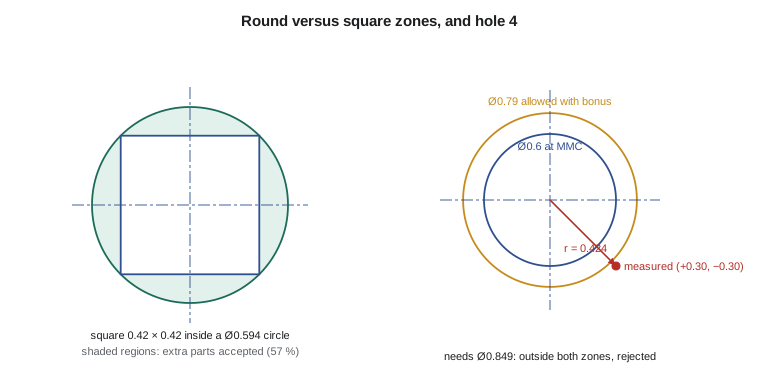
A hole 0.30 mm off in x and 0.30 mm off in y is \(\sqrt{0.30^2 + 0.30^2} = 0.424\) mm from true position, so it needs a zone of diameter 0.849 mm. The factor of two catches nearly everyone the first time: the tolerance is a diameter, the deviation is a radius.
Why round zones are better than square ones
With coordinate tolerancing, a hole located by 10 ± 0.21 and 10 ± 0.21 has a square tolerance zone 0.42 mm on a side. But a mating screw does not care whether the hole is off in x or in y; it cares how far off the hole is in any direction. The square zone allows a hole at its corner to be 0.297 mm from true position while rejecting a hole 0.22 mm off in x alone. A round zone of diameter 0.594 mm passes every hole the square passes and also accepts the holes that are only off in one direction. Its area is 57 percent larger, which means more parts accepted with no loss of function. This is one of the main economic arguments for GD&T.
Material condition modifiers and bonus tolerance
A position tolerance can apply regardless of feature size (RFS), the default in ASME Y14.5-2018, or at maximum material condition (MMC) or least material condition (LMC), indicated by an M or L in a circle after the tolerance value. The MMC modifier is the most common for clearance holes. It says that the stated tolerance applies when the hole is at its smallest size, and that as the hole is made larger, the position tolerance grows by the same amount. This extra allowance is called bonus tolerance.
The logic is functional. A screw passes through a clearance hole if the hole's axis is close enough to the screw's axis. When the hole is at its smallest, MMC, the screw has the least room, so the position must be best. When the hole is larger, the screw has more room and the hole can be farther from true position while still letting the screw pass. Bonus tolerance therefore accepts parts that will assemble, which a fixed tolerance would reject. Functional gauges exploit this: a gauge with fixed pins at true position, each pin at the holes' virtual condition, accepts every part whose holes can accept the screws.
The virtual condition is the worst-case boundary that the feature presents to its mating part, combining size and geometric tolerance. For an internal feature such as a hole at MMC, virtual condition equals MMC minus the position tolerance. For the bracket's holes, 9.0 mm minus 0.6 mm gives a virtual condition of 8.4 mm: whatever the actual size and position of each hole within its tolerances, an 8.4 mm pin at true position will always pass through it.
Worked problem
Reading the inspection report
The bracket's four mounting holes are dimensioned 4X Ø9.0–9.2 with position Ø0.6 at MMC relative to A, B and C, at basic locations 10 and 110 by 10 and 70 mm. Hole 4 measures at (110.30, 69.70) with a diameter of 9.19 mm. Does it pass?
Show solution
- Deviation: \(\Delta x = +0.30\), \(\Delta y = -0.30\) mm, so position \(= 2\sqrt{0.30^2 + 0.30^2} = 0.849\) mm.
- Size: 9.19 mm is within 9.0–9.2 mm, so the hole is acceptable in size.
- Bonus: the hole departs from MMC by \(9.19 - 9.00 = 0.19\) mm, so the allowed position tolerance is \(0.6 + 0.19 = 0.79\) mm.
- Since \(0.849 > 0.79\), hole 4 fails position.
Answer: Hole 4 is rejected. Hole 2, at (110.21, 10.18) and 9.15 mm, has a position of 0.553 mm against an allowed 0.75 mm and passes. Coordinate thinking would have passed hole 4 and possibly rejected hole 2, the opposite of what function requires.
The program evaluates all four holes in the same way, compares square and round zones, and applies the fastener formulas discussed next.
import math

# Mounting holes: 4X diameter 9.0-9.2, position diameter 0.6 at MMC relative to A|B|C.
# True positions (basic) and CMM results, coordinates in mm from datums C (x) and B (y).
basic = {1: (10, 10), 2: (110, 10), 3: (10, 70), 4: (110, 70)}
meas = {1: (10.12, 9.95, 9.08), 2: (110.21, 10.18, 9.15), 3: (9.83, 70.06, 9.02), 4: (110.30, 69.70, 9.19)}
MMC, LMC, pos_tol = 9.0, 9.2, 0.6

print("hole  dx      dy      position  size   bonus  allowed  result")
for k in basic:
    x, y, d = meas[k]
    dx, dy = x - basic[k][0], y - basic[k][1]
    p = 2 * math.hypot(dx, dy)                  # diameter of a zone around true position
    size_ok = MMC <= d <= LMC
    bonus = d - MMC if size_ok else 0.0
    allowed = pos_tol + bonus
    ok = size_ok and p <= allowed
    print(f"{k:>3}  {dx:+.2f}  {dy:+.2f}   {p:.3f}    {d:.2f}   {bonus:.2f}   {allowed:.2f}    {'accept' if ok else 'reject'}")

# Coordinate tolerancing comparison: +/-0.21 square zone versus a round zone that contains it
sq = 0.42
print(f"\nSquare zone {sq} x {sq}: corner-to-corner diagonal = {sq*math.sqrt(2):.3f} mm")
print(f"A round zone that passes every point of that square: diameter {sq*math.sqrt(2):.3f} mm, "
      f"area gain {math.pi*(sq*math.sqrt(2)/2)**2/sq**2 - 1:.0%}")

# Fastener formulas: M8 screws (F = 8.0) through clearance holes of MMC H = 9.0
F, H = 8.0, 9.0
print(f"\nFloating fastener (clearance holes in both parts): T = H - F = {H - F:.1f} mm in each part")
print(f"Fixed fastener (screws into tapped holes): t1 + t2 = H - F = {H - F:.1f} mm, e.g. 0.6 bracket + 0.4 base")

# Virtual condition of the holes: the worst-case mating boundary
print(f"Virtual condition of the bracket holes: MMC - position tolerance = {MMC - pos_tol:.1f} mm")hole dx dy position size bonus allowed result 1 +0.12 -0.05 0.260 9.08 0.08 0.68 accept 2 +0.21 +0.18 0.553 9.15 0.15 0.75 accept 3 -0.17 +0.06 0.361 9.02 0.02 0.62 accept 4 +0.30 -0.30 0.849 9.19 0.19 0.79 reject Square zone 0.42 x 0.42: corner-to-corner diagonal = 0.594 mm A round zone that passes every point of that square: diameter 0.594 mm, area gain 57% Floating fastener (clearance holes in both parts): T = H - F = 1.0 mm in each part Fixed fastener (screws into tapped holes): t1 + t2 = H - F = 1.0 mm, e.g. 0.6 bracket + 0.4 base Virtual condition of the bracket holes: MMC - position tolerance = 8.4 mm
Floating and fixed fastener formulas
Position tolerances for bolted joints follow from simple formulas based on virtual condition. In a floating fastener assembly, a bolt passes through clearance holes in both parts and is secured by a nut; each part can have a position tolerance equal to the difference between the hole's MMC size and the fastener's maximum size, \(T = H - F\). In a fixed fastener assembly, the fastener is restrained in one part, as with a screw in a tapped hole or a press-fit stud, and the total tolerance is shared between the two parts: \(t_1 + t_2 = H - F\).
The bracket bolts to tapped holes in the pump base with M8 screws, a fixed fastener case. With clearance holes at MMC 9.0 mm and screws of 8.0 mm, the total available is 1.0 mm. Farah assigned 0.6 mm to the bracket's holes, which are drilled in a casting, and 0.4 mm to the pump base's tapped holes, which are machined in a single setup. On the inch drawing for the US base, the same logic gives .343 clearance holes for 5/16 screws (.3125), a total of about .030, split .018 and .012. Tapped holes also need a projected tolerance zone, a P in a circle with a height, because a screw follows the tapped hole's axis above the surface, and a small tilt of the thread projects into a large offset at the bracket.
Position of the bearing bore
The bearing bore is located by position too, but without the MMC modifier. A bearing seat does not benefit from bonus tolerance: a larger bore gives a looser bearing, not more room for misalignment. The bore's position is specified as Ø0.05 relative to A, B and C, regardless of feature size, with basic dimensions of 65 mm above A and 60 mm from C. Together with the parallelism of 0.02 mm to A from lesson 9, this keeps the shaft axis where the pump designer expects it.
Profile tolerances
Profile tolerances control the outline of a feature: profile of a line controls each cross-section, and profile of a surface controls the whole surface in three dimensions. The true profile is defined by basic dimensions, often from the model, and the tolerance defines a uniform boundary around it, usually equally disposed, half on each side, unless the U modifier specifies an unequal split. Profile of a surface is the most versatile control in GD&T. Without datums it controls form only; with datums it controls orientation and location as well; and it can control size of irregular features. It is widely used for castings, forgings, molded parts, sheet metal and any curved or complex surface.
On the BB-210, the as-cast outline of the upright and rib carries a profile of a surface tolerance of 1.0 mm relative to A, B and C, which tells the foundry how closely the casting must follow the model. Machined surfaces carry tighter controls. Profile has largely replaced the long lists of ± dimensions that castings used to carry, and in model-based definition a single profile frame applied to all surfaces, with a note such as ALL OVER, can define most of a part's geometry.
Runout
Runout tolerances control surfaces of revolution relative to a datum axis, and they are defined by an inspection: rotate the part 360° about the datum axis and read a dial indicator on the surface. Circular runout limits the indicator reading at each cross-section independently; it controls circularity and coaxiality of each circle. Total runout limits the reading over the whole surface as the indicator also moves along it; it controls cylindricity, straightness, coaxiality and taper together. Runout is natural for turned parts such as shafts, pulleys and hubs, and it replaced concentricity in many uses when the 2018 standard withdrew concentricity, because runout is easy to measure and concentricity was not.
The pump shaft, which is drawn separately, uses total runout of 0.02 mm on its bearing journals relative to a datum axis established by both journals together. The bracket does not need runout, because it has no surfaces of revolution that rotate in service.
How the controls fit together
A complete GD&T scheme on the bracket now reads as a short functional story. Datum A, the mounting face, is flat within 0.05 mm. Datum B, the back face, is perpendicular to A within 0.05 mm. Datum C, the end face, is perpendicular to A and B within 0.1 mm. The bore is 42 H7, cylindrical within 0.01 mm, parallel to A within 0.02 mm and positioned within Ø0.05 to A, B and C. The mounting holes are positioned within Ø0.6 at MMC to A, B and C. The grease pad is at 30° basic to A within angularity 0.2 mm, and its tapped hole is positioned on the pad. The cast surfaces follow the model within profile 1.0 mm. Every requirement relates back to how the part sits on the pump, and nothing on the drawing depends on how a particular machinist chooses to set it up.
Common mistakes
MistakeComparing a hole's x and y deviations directly with the position tolerance.
InsteadCompute the positional deviation as 2√(Δx² + Δy²), a diameter, and compare that.
MistakeApplying MMC to a bearing seat to gain bonus tolerance.
InsteadBonus helps clearance fits for fasteners; bearing seats need location regardless of size.
MistakeForgetting the projected tolerance zone for tapped holes in fixed-fastener joints.
InsteadUse a projected zone equal to the thickness of the mating part.
MistakeUsing concentricity on new ASME Y14.5-2018 drawings.
InsteadUse position, runout or profile; concentricity was removed in 2018.
MistakeTolerancing basic dimensions.
InsteadBasic dimensions are exact; the tolerance is in the feature control frame.
Summary and key terms
- Position locates features of size within zones, usually cylindrical, centered on true position defined by basic dimensions.
- Positional deviation is 2√(Δx² + Δy²); round zones accept 57 percent more area than the inscribed square zone.
- The MMC modifier adds bonus tolerance as a feature departs from MMC; virtual condition is the worst-case mating boundary.
- Floating fasteners allow T = H − F in each part; fixed fasteners share t₁ + t₂ = H − F, with projected zones for tapped holes.
- Profile of a surface controls irregular surfaces and, with datums, their orientation and location as well.
- Circular runout controls each cross-section and total runout the whole surface of a rotating feature.
- A good GD&T scheme reads as a functional description of how the part sits in its assembly.
- True position
- The theoretically exact location of a feature, defined by basic dimensions.
- Position tolerance
- A zone, usually cylindrical, within which the axis or center plane of a feature must lie.
- Bonus tolerance
- Additional position tolerance allowed as a feature of size departs from its MMC.
- Virtual condition
- The worst-case boundary generated by a feature’s MMC and its geometric tolerance.
- Projected tolerance zone
- A zone extended above a feature, such as a tapped hole, to control the mating part.
- Profile of a surface
- A tolerance zone of uniform width around the true profile of a surface.
- Total runout
- A tolerance on indicator readings over a whole surface rotated about a datum axis.
Practice problems
Work each problem on paper first, then reveal the answer to check.
A hole is off by 0.15 mm in x and 0.20 mm in y. What is its positional deviation?
Show answer
2 × 0.25 = 0.50 mm.
A hole Ø10.0–10.3 has position Ø0.2 at MMC. What position is allowed at 10.25 mm?
Show answer
0.2 + 0.25 = 0.45 mm.
What is the virtual condition of that hole?
Show answer
10.0 − 0.2 = 9.8 mm.
Floating fasteners of 6.0 mm pass through holes with MMC 6.6 mm. What position tolerance may each part have?
Show answer
0.6 mm.
Why is MMC not used on the bearing bore?
Show answer
A larger bore does not allow more misalignment; the bearing seat needs its location regardless of size.
In the program, what diameter would hole 4 need to pass?
Show answer
Its allowed tolerance must reach 0.849 mm, so the bonus must be 0.249 mm and the size 9.249 mm, which exceeds LMC 9.2; it cannot pass.
Lesson quiz · 5 questions
Score 60% or more to complete this lesson.
Create a free account to save your progress, take quizzes and earn a certificate.