
MEC-260 · Lesson 7 of 12 · 23 min
Dimensioning practice
When the BB-210 views were finished, Owen dimensioned them the way he had seen in textbooks: every edge got a dimension, chained neatly from left to right. Farah's review took ten minutes and covered the drawing in red. Some features had two dimensions that could disagree; some dimensions referred to rough cast edges that no machinist could measure from; the four mounting holes were located from each other in a chain, so their spacing could drift by three times the tolerance of any single dimension. Nothing on the drawing was wrong in the sense of a false number. It was wrong in the sense that it described the part in a way that did not match how the part works, how it would be made or how Marco would inspect it. This lesson is about dimensioning that does.
What a dimension must do
A dimension states the size of a feature or its location relative to another feature. Together, the dimensions must define every feature completely, with each requirement stated once and only once. ASME Y14.5-2018 lists fundamental rules, and several of them sum up good practice. Each dimension shall have a tolerance, either directly or through a general note. Dimensions shall be complete, so that no feature's size, location or shape has to be assumed or scaled. Each necessary dimension shall appear once, and dimensions that are not needed shall be omitted. The drawing shall define the part without specifying manufacturing methods, unless the method is essential to function. And dimensions shall be arranged for optimum readability, shown in true profile views and not to hidden lines.
The rule about not specifying methods is often misunderstood. It means that a drawing should say what the part must be, a hole 9 mm in diameter at a given location, rather than how to make it, drill with a 9 mm drill. The supplier may drill, ream, mill, laser cut or cast the hole, as long as the result meets the drawing. Exceptions exist where the process affects function, such as a required heat treatment or a surface that must not be ground, and those are given as notes.
Size and location dimensions
Dimensions fall into two types. Size dimensions give the size of a feature: the diameter of a hole, the width of a slot, the thickness of a plate. Location dimensions give the position of a feature relative to another feature or to a datum: the distance from an edge to a hole center, the height of a bore center above a mounting face. A useful habit, borrowed from manufacturing, is to break the part into simple geometric shapes, such as prisms, cylinders, holes and slots, give each one its size dimensions, and then locate each one relative to the others or to a reference surface.
Holes and cylinders are always located by their centers, not their edges, because centers are what fit with mating parts and what machines and inspection equipment work from. Cylinders are dimensioned by diameter in the view where they appear as rectangles, or with a leader in the circular view; arcs of less than a full circle are dimensioned by radius.
Elements of a dimension
A dimension consists of thin extension lines that extend from the feature with a small visible gap from the object, a thin dimension line between them with arrowheads, and the dimension value, centered on the dimension line. ASME practice uses unidirectional dimensioning, in which all values read from the bottom of the sheet; ISO practice also allows aligned dimensioning, read from the bottom or the right. Leaders, thin lines with an arrowhead or dot, point from a note to a feature. Spacing matters: the first dimension line sits about 10 mm from the view, and further parallel dimension lines about 6 mm apart, with shorter dimensions placed nearer the view so that extension lines do not cross dimension lines.
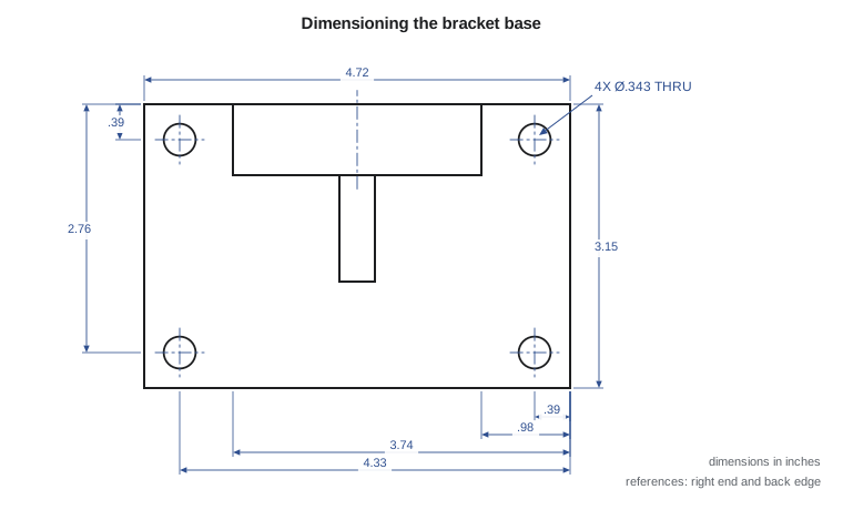
Standard symbols replace many words in notes, which makes drawings shorter and language-neutral. The diameter symbol Ø precedes a diameter. R precedes a radius, SR a spherical radius and SØ a spherical diameter. The counterbore symbol, a small square bracket open at the top, the countersink symbol, a V, and the depth symbol, a down arrow with a bar, combine into compact hole notes. The square symbol □ indicates a square shape. The notation 4X means four places; it replaces the old practice of writing TYP, which ASME discourages because it is ambiguous. Reference dimensions, given for information only and not used for manufacturing or inspection, are enclosed in parentheses. Basic dimensions, the theoretically exact values used with geometric tolerances (lesson 10), are enclosed in rectangles.
| Symbol or notation | Meaning | Example |
|---|---|---|
| Ø | Diameter | Ø42 |
| R / SR | Radius / spherical radius | R35 |
| nX | Number of places | 4X Ø9 THRU |
| Counterbore + depth | Flat-bottomed enlargement of a hole | Ø9 THRU, counterbore Ø15 depth 8 |
| Countersink | Conical enlargement of a hole | Ø6.6 THRU, countersink Ø13 × 90° |
| Depth | Depth of a hole or feature | Ø5 depth 12 |
| (value) | Reference dimension, not toleranced | (120) |
| Boxed value | Basic dimension for geometric tolerancing | a boxed 100 |
| Square symbol | Square feature | square 20 |
Units, decimals and zeros
Inch drawings give dimensions in decimal inches. ASME inch practice omits the zero before the decimal point, as in .50, and adds trailing zeros so that a dimension has the same number of places as its tolerance: 1.500 ± .005, not 1.5 ± .005. The number of places can imply precision on drawings that use a general tolerance block, for example ± .02 for two-place and ± .005 for three-place dimensions, which is why writing 1.5 instead of 1.500 can change the tolerance. Metric drawings, which Tidewater uses for export pumps, follow the opposite convention: a leading zero, as in 0.5, and no trailing zeros except to match tolerance limits, as in 42.025 and 42.000.
Angles are dimensioned in degrees, and in minutes and seconds or decimal degrees when needed: 30°, 12.5° or 12°30′. Angular dimensions use arcs centered on the vertex of the angle. The grease pad on the BB-210 carries an angle of 30° from horizontal, dimensioned in the side view where the pad appears as an edge.
Choosing what to dimension from
The most important decision in dimensioning is choosing the features from which other features are located. These should be the features that matter for function and that can be used in manufacture and inspection: machined mounting faces, bore axes, locating pins and edges that contact mating parts. On the BB-210, the bottom of the base bolts to the pump base, so heights are dimensioned from it. The machined back face, which sits against a shoulder on the pump base, and the machined right end face, which butts against a stop, are the references for horizontal positions. The bore center is located from these, and the mounting holes are located from them too. In the language of lesson 9 these become datums, but the principle applies even without geometric tolerancing.
Dimensioning from rough cast surfaces is a common error. A cast surface varies from casting to casting, often by a millimeter or more, and a machinist cannot set up from it reliably. Cast features should be located from a single rough reference only where necessary, typically to locate the first machining operation, and all machined features should be dimensioned from machined references.
Chain, baseline and ordinate dimensioning
There are three common ways to arrange location dimensions along one direction. Chain dimensioning places dimensions end to end, each from the previous feature. Baseline dimensioning measures every feature from a common reference. Ordinate dimensioning is a compact form of baseline dimensioning, with each feature labeled with its coordinate from a zero line and no dimension lines; it suits parts with many holes, such as plates and sheet-metal parts, and matches how CNC machines are programmed.
The choice matters because tolerances accumulate. With chain dimensioning, the distance between two features separated by several dimensions can vary by the sum of their tolerances. With baseline dimensioning, the distance between any feature and the baseline varies only by one tolerance, though the distance between two features not involving the baseline can vary by two. The best choice is to dimension directly between features whose relationship matters. If the two mounting holes must be 100 mm apart to fit the pump base, give a 100 mm dimension between them, or locate both from the same reference.
Worked problem
Tolerance stack on the mounting holes
Along the length of the base, five features lie at nominal distances 0 (the end face), 10 (first hole), 25 and 95 (faces of the upright) and 110 (second hole) mm. Every dimension is toleranced ± 0.10 mm. Compare the possible variation of the hole spacing with chain and baseline dimensioning.
Show solution
- Chain dimensioning gives four dimensions: 10, 15, 70 and 15. The holes are separated by three of them, so their spacing can vary by \(3 \times 0.10 = \pm 0.30\) mm: from 99.70 to 100.30 mm.
- Baseline dimensioning from the end face gives 10, 25, 95 and 110. The hole spacing is the difference between two dimensions, so it can vary by \(2 \times 0.10 = \pm 0.20\) mm: from 99.80 to 100.20 mm.
- A direct 100 mm dimension between the holes gives \(\pm 0.10\) mm: from 99.90 to 100.10 mm.
Answer: If the mounting screws need the spacing within ± 0.15 mm, chain dimensioning fails, baseline dimensioning fails, and only the direct dimension, or a geometric position tolerance referenced to common datums, states the real requirement. Dimension what matters directly.
The program tabulates the worst-case variation between every pair of features under both schemes, which makes the trade-off visible: chain dimensioning controls adjacent features tightly and distant ones loosely, while baseline dimensioning does the reverse.
# Tolerance accumulation: chain versus baseline dimensioning.
# Five features along the bracket base, nominal positions from the machined end face (mm).
pos = [0, 10, 25, 95, 110]   # end face, hole, upright face, upright face, hole
tol = 0.10                       # every dimension toleranced +/- 0.10 mm

def chain(pos, tol):
    steps = [b - a for a, b in zip(pos, pos[1:])]
    worst = {}
    for i in range(len(pos)):
        for j in range(i + 1, len(pos)):
            n = j - i                       # dimensions between feature i and feature j
            worst[(i, j)] = n * tol
    return steps, worst

def baseline(pos, tol):
    worst = {}
    for i in range(len(pos)):
        for j in range(i + 1, len(pos)):
            n = (1 if i == 0 else 2)        # from the datum edge: one dimension, or two between features
            worst[(i, j)] = n * tol
    return worst

steps, wc = chain(pos, tol)
wb = baseline(pos, tol)
print("Chain dimensions:", steps)
print("Baseline dimensions from the end face:", pos[1:])
print("\nWorst-case variation between features (mm):")
print("  pair      chain   baseline")
for (i, j) in [(0, 4), (1, 4), (1, 2), (2, 3), (3, 4)]:
    print(f"  {i}-{j}      +/-{wc[(i, j)]:.2f}   +/-{wb[(i, j)]:.2f}")

# The two mounting holes are features 1 and 4: 100 mm apart nominally.
print("\nHole-to-hole spacing 1-4 (nominal 100 mm):")
print(f"  chain:    {100 - wc[(1, 4)]:.2f} to {100 + wc[(1, 4)]:.2f}")
print(f"  baseline: {100 - wb[(1, 4)]:.2f} to {100 + wb[(1, 4)]:.2f}")
print(f"  direct dimension between the holes: {100 - tol:.2f} to {100 + tol:.2f}")

# The same spacing on an inch drawing: 3.937 in nominal, +/- .004 per dimension
print(f"\nInch equivalent of 100 mm: {100/25.4:.3f} in; 0.10 mm = {0.10/25.4:.4f} in")Chain dimensions: [10, 15, 70, 15] Baseline dimensions from the end face: [10, 25, 95, 110] Worst-case variation between features (mm): pair chain baseline 0-4 +/-0.40 +/-0.10 1-4 +/-0.30 +/-0.20 1-2 +/-0.10 +/-0.20 2-3 +/-0.10 +/-0.20 3-4 +/-0.10 +/-0.20 Hole-to-hole spacing 1-4 (nominal 100 mm): chain: 99.70 to 100.30 baseline: 99.80 to 100.20 direct dimension between the holes: 99.90 to 100.10 Inch equivalent of 100 mm: 3.937 in; 0.10 mm = 0.0039 in
Placement and readability
Dimensions should be placed in the view that shows the feature's true shape most clearly, usually its most characteristic view: the diameter of the bore in the side section where its depth also appears, the hole pattern in the top view where the holes appear as circles. Dimensions should be placed outside the views where possible, grouped between views when they relate features in both, and kept off the object. Avoid crossing extension lines with dimension lines, avoid dimensioning to hidden lines, and avoid long leaders that wander across the view. Where a dimension must sit inside a hatched area, interrupt the hatching around it.
Overdimensioning, giving the same requirement twice, is a frequent and serious error. If a drawing gives the overall length and every individual length along the same line, one of them is redundant, and if the tolerances do not add up the drawing contradicts itself. Either omit one dimension or mark it as a reference dimension in parentheses. Underdimensioning, leaving a feature's size or location undefined, is equally serious; the supplier will make an assumption, and the model's nominal value may not be what the designer intended.
Notes
Notes complete the definition. General notes apply to the whole drawing and are usually placed near the title block: units, the governing standard, general tolerances, material treatments, edge breaks such as BREAK SHARP EDGES 0.2 TO 0.5, unspecified fillets such as ALL CAST FILLETS R3, surface texture requirements and finishes. Local notes apply to one feature and are attached with a leader: the counterbore specification of a hole, a thread callout, a knurl. Notes should be short, upper case, written as instructions, and free of abbreviations that are not standard.
Surface texture, the roughness of a machined surface, is specified with a check-mark symbol and a roughness value, usually as the average roughness Ra in micrometers on metric drawings or microinches on inch drawings. The BB-210 bore needs Ra 0.8 µm for the bearing fit; the mounting face needs Ra 3.2 µm; cast surfaces are left as cast. ISO 1302 and its successor ISO 21920, and ASME Y14.36, define the symbols.
Common mistakes
MistakeDimensioning holes to their edges instead of their centers.
InsteadLocate holes and cylinders by their centers; mating parts and machines work from axes.
MistakeChaining dimensions between features whose relationship matters.
InsteadDimension critical relationships directly or from a common reference.
MistakeGiving the overall dimension and every intermediate dimension along one line.
InsteadOmit one, or show it as a reference dimension in parentheses.
MistakeDimensioning machined features from rough cast surfaces.
InsteadLocate machined features from machined, functional references.
MistakeUsing TYP to show repeated features.
InsteadUse nX notation, such as 4X Ø9 THRU, which is unambiguous.
Summary and key terms
- Each feature must be fully defined once, with a tolerance, without specifying methods unless function requires it.
- Size dimensions give feature sizes; location dimensions position features, always to centers for holes and cylinders.
- Standard symbols such as Ø, R, nX, counterbore, countersink, depth, reference and basic dimensions keep notes short and clear.
- Metric and inch drawings follow opposite conventions for leading and trailing zeros.
- Dimension from functional, machined references, not from rough cast surfaces.
- Chain dimensioning accumulates tolerance; baseline and direct dimensions control critical relationships.
- Avoid overdimensioning and underdimensioning; general and local notes complete the definition.
- Size dimension
- A dimension giving the size of a feature.
- Location dimension
- A dimension locating a feature relative to another feature or reference.
- Chain dimensioning
- Dimensions placed end to end, each from the previous feature.
- Baseline dimensioning
- Dimensions measured from a common reference line or surface.
- Ordinate dimensioning
- Coordinates labeled from a zero line without dimension lines.
- Reference dimension
- A dimension for information only, shown in parentheses and not toleranced.
- Basic dimension
- A theoretically exact dimension, shown boxed, used with geometric tolerances.
- General note
- A note that applies to the whole drawing.
Practice problems
Work each problem on paper first, then reveal the answer to check.
A drawing gives 120 overall and 10, 15, 70, 15 and 10 along the same line. What is wrong?
Show answer
It is overdimensioned; one dimension should be omitted or shown as a reference.
Write a note for four through holes of 9 mm diameter.
Show answer
4X Ø9 THRU.
How would 0.5 inch be written on an inch drawing with a ± .005 tolerance?
Show answer
.500 ± .005.
Why should the bore of the bracket be located from the mounting face rather than the top of the upright?
Show answer
The mounting face is machined and functional; the top of the upright is cast and varies.
Three chained dimensions of ± 0.05 mm separate two features. What is the worst-case variation of their distance?
Show answer
± 0.15 mm.
In the program, what tolerance per dimension would hold the chain-dimensioned hole spacing to ± 0.15 mm?
Show answer
± 0.05 mm, since three dimensions accumulate.
Lesson quiz · 5 questions
Score 60% or more to complete this lesson.
Create a free account to save your progress, take quizzes and earn a certificate.