
MEC-260 · Lesson 8 of 12 · 23 min
Tolerances, limits and fits
The forty scrapped castings that Farah mentioned on Owen's first day had a simple cause. The old drawing gave the bearing bore as 42 with no tolerance of its own, so it fell under the general tolerance of ± 0.2 mm. The machine shop bored the castings to 42.15 mm, comfortably inside that tolerance, and the bearings were loose enough to spin in their housings. Fretting wore the bores within months. The bore needed a tolerance of a few hundredths of a millimeter, chosen to give a specific relationship with the bearing's outer ring. This lesson covers how tolerances are specified, how standard fits are chosen, and how tolerances add up in an assembly.
Why every dimension has a tolerance
No process makes parts exactly to size. A machine tool's position drifts with temperature, cutting tools wear, castings shrink differently each time, and measuring instruments have their own uncertainty. A tolerance is the total amount a dimension may vary, and it states the designer's decision about how much variation the function can accept. Tolerances drive cost strongly: tightening a tolerance often means a slower process, a more precise machine, extra operations such as grinding or reaming, more inspection and more scrap. A good designer makes tolerances as loose as function allows and tight only where function demands it.
Tolerances can be expressed in several ways. Limit dimensioning gives the upper and lower limits directly, with the upper limit on top: 42.025 over 42.000. Plus-and-minus tolerancing gives a nominal value and deviations, either bilateral, varying in both directions such as 65 ± 0.05, or unilateral, varying in one direction only such as 42 +0.025/0. A general tolerance in the title block covers all dimensions without their own tolerance, often as a table by size range or by number of decimal places, or by reference to ISO 2768, which defines general tolerance classes such as fine, medium, coarse and very coarse.
Terms of limits and fits
The language of fits is precise, and ISO 286 and ANSI B4.1 use nearly the same terms. The nominal size, or basic size in older usage, is the size from which limits are derived, such as 42 mm. The upper and lower limits are the largest and smallest allowed sizes. The deviation is the difference between a limit and the nominal size: the upper deviation (ES for holes, es for shafts) and the lower deviation (EI for holes, ei for shafts). The tolerance is the difference between the limits. The fundamental deviation is the deviation closest to the nominal size, which fixes where the tolerance zone sits relative to the nominal.
A fit is the relationship between two mating parts, conventionally called the hole and the shaft even when they are slots and keys or bores and bearing rings. A clearance fit always leaves a gap; an interference fit always requires force or heat to assemble because the shaft is always larger than the hole; a transition fit may give either, depending on where the actual sizes fall. The allowance, in North American usage, is the tightest condition: the minimum clearance or maximum interference.
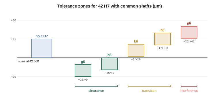
The ISO system: grades and letters
ISO 286 builds every tolerance zone from two parts. The size of the zone comes from a standard tolerance grade, IT01 to IT18, where smaller numbers mean tighter tolerances. Each grade is a multiple of a tolerance unit that grows with size, because larger parts are harder to make precisely: for sizes up to 500 mm, \(i = 0.45\sqrt[3]{D} + 0.001D\) micrometers, with \(D\) the geometric mean of the size range in millimeters. IT6 is 10i, IT7 is 16i, IT8 is 25i and IT11 is 100i. As a rough guide, IT5 to IT7 are achieved by grinding, honing and fine boring; IT7 to IT9 by reaming, boring and precision turning; IT10 to IT12 by milling, drilling and ordinary turning; and IT14 and coarser by casting and forging.
The position of the zone comes from a letter: capital letters for holes, lower case for shafts. For holes, H means the lower deviation is zero, so the hole is never smaller than nominal. For shafts, h means the upper deviation is zero, so the shaft is never larger than nominal. Letters before h (a to g for shafts) give shafts smaller than nominal and therefore clearance with an H hole; letters after h (j to zc) give progressively larger shafts and transition or interference. A complete specification is written as the nominal size, the hole zone and the shaft zone, for example 42 H7/g6.
Hole basis and shaft basis
Most fits are specified on a hole-basis system, in which the hole is H and the shaft letter is chosen to give the fit. The reason is practical: holes are usually made with fixed-size tools such as reamers and checked with fixed plug gauges, so standardizing the hole reduces tooling, while shafts are turned or ground to any size with the same tools. A shaft-basis system, with an h shaft and varying holes, is used when one shaft carries several parts with different fits, as with drawn bar stock or a shaft that passes through several bearings and pulleys.
ISO publishes preferred fits that cover most needs. On a hole basis, H11/c11 is a loose running fit; H9/d9 a free running fit; H8/f7 a close running fit; H7/g6 a sliding fit for accurate location with free movement; H7/h6 a locational clearance fit; H7/k6 a locational transition fit; H7/n6 a tighter locational transition fit; H7/p6 a locational interference fit; H7/s6 a medium drive fit; and H7/u6 a force fit. Designers start from these and depart from them only with a reason.
Worked problem
Limits of a sliding fit
Find the limits and the fit for 42 H7/g6. In the 30–50 mm range, IT6 = 16 µm, IT7 = 25 µm, and the fundamental deviation for g is es = −9 µm.
Show solution
- Hole H7: EI = 0, ES = +25 µm, so the hole is 42.000 to 42.025 mm.
- Shaft g6: es = −9 µm, ei = −9 − 16 = −25 µm, so the shaft is 41.975 to 41.991 mm.
- Maximum clearance = largest hole − smallest shaft = 42.025 − 41.975 = 0.050 mm.
- Minimum clearance = smallest hole − largest shaft = 42.000 − 41.991 = 0.009 mm.
Answer: The fit always has clearance, between 9 and 50 µm: a precise sliding fit. The tolerance unit formula reproduces the table: with D = 38.73 mm, i = 1.561 µm and IT7 = 16i = 25.0 µm.
The program computes the tolerance grades from the formula, then uses the published values for the 30–50 mm range to list the limits and fit type for 42 H7 with five common shafts, and checks the bearing fit discussed below.
import math

# ISO 286: standard tolerance grades from the tolerance unit i (um),
# using the geometric mean D of the size range (mm).
def tol_unit(D): return 0.45 * D ** (1 / 3) + 0.001 * D
mult = {5: 7, 6: 10, 7: 16, 8: 25, 9: 40, 10: 64, 11: 100}

lo, hi = 30, 50                 # ISO size range containing 42 mm
D = math.sqrt(lo * hi)
i = tol_unit(D)
print(f"Size range {lo}-{hi} mm: geometric mean D = {D:.2f} mm, tolerance unit i = {i:.3f} um")
for g in (6, 7, 8):
    print(f"  IT{g} = {mult[g]} i = {mult[g]*i:.1f} um")

# Published ISO 286-2 values for the 30-50 mm range (um)
IT = {6: 16, 7: 25, 8: 39}
fund = {'f': ('es', -25), 'g': ('es', -9), 'h': ('es', 0), 'k': ('ei', 2), 'n': ('ei', 17), 'p': ('ei', 26)}
def shaft(letter, grade):
    kind, dev = fund[letter]
    return (dev - IT[grade], dev) if kind == 'es' else (dev, dev + IT[grade])
def hole_H(grade): return (0, IT[grade])

print(f"\nFormula check, g fundamental deviation: es = -2.5 D^0.34 = {-2.5 * D ** 0.34:.1f} um (table: -9)")

nominal = 42.0
H7 = hole_H(7)
print(f"\nHole 42 H7: {nominal + H7[0]/1000:.3f} to {nominal + H7[1]/1000:.3f} mm")
for fit in ('g6', 'h6', 'k6', 'n6', 'p6'):
    s = shaft(fit[0], int(fit[1]))
    cmax = H7[1] - s[0]; cmin = H7[0] - s[1]
    kind = 'clearance' if cmin >= 0 else ('interference' if cmax <= 0 else 'transition')
    print(f"  H7/{fit}: shaft {nominal + s[0]/1000:.3f} to {nominal + s[1]/1000:.3f};"
          f" max {cmax:+d} um, min {cmin:+d} um -> {kind}")

# The bearing outer ring (normal tolerance class, OD 30-50 mm: 0 / -11 um) in the H7 bore
od = (-11, 0)
print(f"\nBearing OD 42 (0/-11) in 42 H7: clearance from {H7[0]-od[1]:+d} to {H7[1]-od[0]:+d} um")

# Stack-up: height of the shaft axis above the pump base, four contributors (mm)
stack = [('shim', 2.00, 0.05), ('mounting face to bore axis', 65.00, 0.05),
         ('bearing radial runout allowance', 0.00, 0.01), ('base pad flatness', 0.00, 0.03)]
nom = sum(n for _, n, _ in stack)
wc = sum(t for _, _, t in stack)
rss = math.sqrt(sum(t * t for _, _, t in stack))
print(f"\nShaft height stack: nominal {nom:.2f} mm, worst case +/-{wc:.3f}, RSS +/-{rss:.3f}")Size range 30-50 mm: geometric mean D = 38.73 mm, tolerance unit i = 1.561 um IT6 = 10 i = 15.6 um IT7 = 16 i = 25.0 um IT8 = 25 i = 39.0 um Formula check, g fundamental deviation: es = -2.5 D^0.34 = -8.7 um (table: -9) Hole 42 H7: 42.000 to 42.025 mm H7/g6: shaft 41.975 to 41.991; max +50 um, min +9 um -> clearance H7/h6: shaft 41.984 to 42.000; max +41 um, min +0 um -> clearance H7/k6: shaft 42.002 to 42.018; max +23 um, min -18 um -> transition H7/n6: shaft 42.017 to 42.033; max +8 um, min -33 um -> transition H7/p6: shaft 42.026 to 42.042; max -1 um, min -42 um -> interference Bearing OD 42 (0/-11) in 42 H7: clearance from +0 to +36 um Shaft height stack: nominal 67.00 mm, worst case +/-0.140, RSS +/-0.077
Inch fits: ANSI B4.1
US inch drawings use ANSI B4.1, which defines classes of fits by function rather than by letter and grade. Running and sliding fits are RC1 to RC9, from close sliding fits for precise location to loose running fits for agricultural machinery. Locational fits are LC (clearance), LT (transition) and LN (interference) classes. Force and shrink fits are FN1 to FN5, from light drive fits to heavy shrink fits. Each class gives limits in thousandths of an inch for each size range, and an inch drawing states the resulting limits, such as 1.6535 over 1.6545 for a bore, rather than the class name alone. ANSI B4.2 is the US metric counterpart and uses the ISO letters and grades.
Whatever system is used, the drawing must state the result in a form the shop can use: either the ISO designation with the limits added in parentheses, such as 42 H7 (42.025/42.000), or the limits alone. Writing only H7 forces every machinist and inspector to look up the table, and an error in that lookup produces scrap that looks correct.
Fits for rolling bearings
Bearings are a special case because their rings are made to their own standard tolerances, which the designer cannot change. Bearing bores and outside diameters for the normal tolerance class follow ISO 492, and both are toleranced below nominal: for a 42 mm outside diameter, the ring is 0 to −11 µm. The housing and shaft fits are then chosen from the bearing maker's guidelines, which depend mainly on which ring rotates relative to the load. The ring that rotates relative to the load needs an interference fit, or it will creep and wear its seat. The ring that is stationary relative to the load can have a clearance or transition fit, which eases assembly and lets the ring move axially as the shaft grows with temperature.
In the pump, the shaft and the inner ring rotate while the load direction stays fixed, so the inner ring gets an interference fit on the shaft, typically k5 or k6, and the outer ring sits in the bracket with a clearance or light transition fit. Farah chose 42 H7 for the bore. With the bearing ring at 0 to −11 µm and the bore at 0 to +25 µm, the clearance ranges from zero to 36 µm, which supports the ring fully while allowing it to slide axially as a floating bearing.
Tolerance stack-up
Tolerances on individual parts combine in an assembly. A tolerance stack-up adds the dimensions and tolerances along a chain of parts to find the variation of a gap, a height or an alignment. The worst-case method adds the tolerances directly, guaranteeing that every assembly works even if every part is at its worst limit at the same time. It is safe but expensive, because it forces tight tolerances on every part. The statistical, or root-sum-square (RSS), method assumes that part dimensions vary randomly and independently, usually with a normal distribution centered on nominal, so that extremes rarely combine. It predicts a smaller assembly variation:
For the pump, the height of the shaft axis above the base depends on a shim (2.00 ± 0.05 mm), the bracket's bore height above its mounting face (65.00 ± 0.05 mm), and smaller contributions from the bearing's runout and the flatness of the base pad. The worst-case variation is ± 0.14 mm; the RSS estimate is ± 0.077 mm. If the coupling can accept ± 0.10 mm of offset, the worst-case method says the design fails and the RSS method says it usually works. The choice of method is a business decision about risk: RSS is appropriate for high-volume parts made by stable, centered processes, while worst case is appropriate for low volumes, safety-critical assemblies or processes that are not well controlled. Many companies use RSS with an inflation factor, or a Monte Carlo simulation using measured process data.
Tolerances and cost
Tighter tolerances cost more, and the cost rises steeply near the limit of a process. A tolerance that can be held by turning may cost little more than an untoleranced dimension; halving it may require grinding, an extra setup and full inspection. Designers can reduce cost by choosing standard fits that match standard tooling, by using selective assembly for a few critical fits, by designing adjustment into an assembly with shims or slotted holes, and by tolerancing features relative to the functional datums that really matter, which is the subject of geometric tolerancing in the next two lessons.
Common mistakes
MistakeSpecifying only an ISO fit designation without the numerical limits.
InsteadAdd the limits in parentheses or give limits directly so the shop does not need a table lookup.
MistakeChoosing a tight fit for a bearing's stationary ring.
InsteadThe ring rotating relative to the load gets the interference fit; the stationary ring usually gets clearance or transition.
MistakeAssuming a bore under the general tolerance is good enough for a bearing.
InsteadBearing seats need specific fits a few hundredths of a millimeter wide.
MistakeAlways using worst-case stack-ups regardless of volume and process.
InsteadConsider RSS or Monte Carlo methods for stable, high-volume processes, with appropriate safety margins.
MistakeTightening every tolerance in a stack equally.
InsteadFind and reduce the dominant contributors first.
Summary and key terms
- Every dimension has a tolerance, which states how much variation function can accept and strongly affects cost.
- Tolerances are given as limits, bilateral or unilateral deviations, or general tolerances such as ISO 2768.
- ISO 286 zones combine a tolerance grade (IT number) for size and a letter for position; H holes and h shafts start at nominal.
- Fits are clearance, transition or interference; hole-basis systems with preferred fits such as H7/g6 and H7/k6 are most common.
- ANSI B4.1 inch fits use functional classes RC, LC, LT, LN and FN.
- Bearing fits follow the rule that the ring rotating relative to the load needs interference.
- Worst-case stack-ups add tolerances; RSS stack-ups add them in quadrature and assume random, centered variation.
- Tolerance
- The total permissible variation of a dimension, the difference between its limits.
- Fundamental deviation
- The deviation nearest the nominal size, which locates the tolerance zone.
- Standard tolerance grade
- An ISO IT number defining the size of a tolerance zone relative to the nominal size.
- Clearance fit
- A fit that always leaves a gap between mating parts.
- Interference fit
- A fit in which the shaft is always larger than the hole.
- Transition fit
- A fit that may give clearance or interference depending on actual sizes.
- Hole-basis system
- A system of fits in which the hole has a fixed H zone and the shaft zone is varied.
- Tolerance stack-up
- An analysis of how tolerances on several parts combine in an assembly.
Practice problems
Work each problem on paper first, then reveal the answer to check.
For 42 H7/h6 (IT6 = 16 µm, IT7 = 25 µm), what are the maximum and minimum clearances?
Show answer
Maximum 41 µm, minimum 0.
Is 42 H7/n6 a clearance, transition or interference fit?
Show answer
Transition: from 8 µm clearance to 33 µm interference.
Using the tolerance unit, estimate IT8 for the 30–50 mm range.
Show answer
25 × 1.561 = 39 µm.
Five parts each toleranced ± 0.02 mm form a stack. What are the worst-case and RSS variations?
Show answer
± 0.10 mm and ± 0.045 mm.
Why is a hole-basis system usually preferred?
Show answer
Holes are made and gauged with fixed-size tools, so standardizing the hole reduces tooling.
In the program, change the shim tolerance to ± 0.02 mm. What are the new worst-case and RSS results?
Show answer
Worst case ± 0.110 mm; RSS about ± 0.063 mm.
Lesson quiz · 5 questions
Score 60% or more to complete this lesson.
Create a free account to save your progress, take quizzes and earn a certificate.