
MEC-260 · Lesson 11 of 12 · 23 min
Threads, fasteners and standard parts on drawings
The BB-210 has only three threaded features: the four clearance holes for the mounting screws, the tapped hole for the grease fitting on the inclined pad, and two tapped holes on the upright for the bearing cover. Yet these small features generated more questions from the machine shop than the rest of the part combined. Was the grease hole metric or a pipe thread? How deep did the thread need to go, and how deep was the drill? Which screws were meant, and how hard should they be tightened? Engineers rarely draw threads in detail, because threads, fasteners, bearings, keys and springs are standard parts defined by standards and catalogs. What they must do is call them out completely and represent them conventionally. This lesson covers how.
Thread terminology
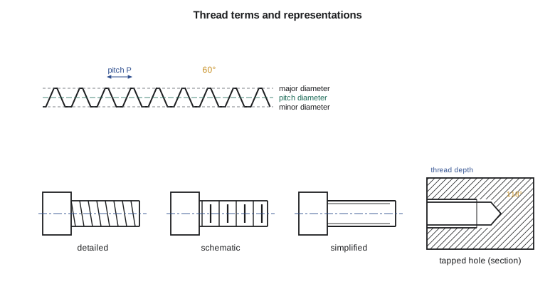
A screw thread is a helical ridge on a cylinder (external thread) or in a hole (internal thread). The major diameter is the largest diameter of the thread, the nominal size for most systems. The minor diameter is the smallest. The pitch diameter lies between them, where the thread ridge and the groove are equal in width, and it is the diameter that controls how well mating threads fit. The pitch, P, is the distance from one thread to the next, measured parallel to the axis. Inch threads are described by threads per inch, n, so the pitch is \(1/n\). The lead is the distance the thread advances in one turn: equal to the pitch for a single-start thread, twice the pitch for a double-start thread. Threads are right-hand unless marked LH, and ISO metric and unified threads share a 60° thread angle.
Metric and unified designations
ISO metric threads are designated by the letter M, the nominal diameter and, for fine threads, the pitch: M8 is an 8 mm coarse thread with the standard 1.25 mm pitch, and M8×1 is a fine thread with 1 mm pitch. The coarse pitch is assumed when no pitch is written, although many companies write it anyway to avoid doubt. A tolerance class follows: 6H for internal threads and 6g for external threads are the general-purpose medium classes, written M8×1.25-6H or M8-6g. The number is the tolerance grade, the letter the position, borrowing the logic of ISO 286. Coarse threads suit most applications, especially in softer materials like aluminum, because the deeper, wider threads strip less easily; fine threads give finer adjustment and slightly higher strength in thin walls and hard materials.
Unified inch threads, defined by ASME B1.1, are designated by the nominal diameter, threads per inch, series and class: 5/16-18 UNC-2A is a 5/16 inch coarse thread with 18 threads per inch, class 2A. UNC is the coarse series, UNF the fine series and UNEF extra fine. Classes 1, 2 and 3 run from loose to tight; A means external and B internal. Class 2A and 2B are the general-purpose classes, the inch equivalent of 6g and 6H. Small sizes are given by number, such as #10-24 UNC.
Tidewater designs export pumps in metric, so the bracket uses M8 mounting screws and M6 threads, but the inch drawings for older US pump bases call for 5/16-18 UNC. Pipe threads are a separate system again. Tapered pipe threads seal by wedging and are designated NPT in the inch system or R and Rc under ISO 7-1; straight pipe threads are NPS or G under ISO 228. Many grease fittings use 1/4-28 straight threads or 1/8 NPT, and confusing a G1/8 thread with a 1/8 NPT thread is a classic mistake: they look alike but have different angles and pitches. The BB-210 grease hole is M6×1, matching the fitting the company standardizes on.
| Thread | Pitch | Tap drill | Tensile stress area |
|---|---|---|---|
| M6 | 1.0 mm | 5.0 mm | 20.1 mm² |
| M8 | 1.25 mm | 6.8 mm | 36.6 mm² |
| M10 | 1.5 mm | 8.5 mm | 58.0 mm² |
| 1/4-20 UNC | 0.050 in | #7 (0.201 in) | 0.0318 in² |
| 5/16-18 UNC | 0.0556 in | F (0.257 in) | 0.0524 in² |
| 3/8-16 UNC | 0.0625 in | 5/16 in | 0.0775 in² |
Representing threads
Standards define three ways to draw threads. Detailed representation draws the helix and the crests realistically; it is slow and is used only for large threads, presentations or when the thread form itself is the subject. Schematic representation uses alternating lines for crests and roots and is now rare. Simplified representation, the norm on detail drawings, shows an external thread by its major diameter as a visible line and its minor diameter as a thin line (or a dashed line where hidden), and an internal thread by its minor diameter as the hole outline with the major diameter as a thin or dashed line. In end views, the major diameter of an external thread is a thick circle and the minor diameter a thin three-quarter circle; for an internal thread, the reverse. ASME Y14.6 and ISO 6410 define the details. 3D models usually show threads as plain cylinders with a cosmetic thread attribute, which produces the simplified representation on the drawing.
The callout carries the real information. A tapped hole note gives the drill and the thread, with depths, for example Ø5 depth 12, M6×1-6H depth 9, using the depth symbol. A through tapped hole needs no depth. Thread depth means the length of full thread; the drilled hole must be deeper, by at least a few pitches, because a tap cannot cut full threads to the bottom of a blind hole, and the drill point leaves a cone at the bottom, conventionally drawn at 118°. The drill depth is measured to the end of the full diameter, not to the point.
Worked problem
Specifying the grease hole
The grease fitting needs an M6×1 thread in the inclined pad. The pad gives about 12 mm of material before a 3 mm drilled passage breaks into the bearing bore. How should the hole be specified?
Show solution
- Tap drill for M6×1: approximately \(d - P = 6 - 1 = 5.0\) mm.
- Allow about three pitches beyond the full thread for the tap's lead: with 9 mm of full thread, drill \(9 + 3 \times 1 = 12\) mm deep.
- Engagement is \(9/6 = 1.5\) diameters, which is adequate for a grease fitting that carries no structural load in a cast aluminum part.
- Callout, in VIEW B on the pad: Ø5 depth 12, M6×1-6H depth 9, followed by a separate note for the Ø3 passage to the bore.
Answer: The note specifies the result, a 6H thread 9 mm deep, and the drill size and depth that make it possible. The shop may substitute a different tap or a thread-forming tool, as long as the thread gauges correctly.
The program lists tap drills and tensile stress areas for common metric and unified threads, checks the engagement of the grease hole, and estimates the proof load of the mounting screws.
import math

# ISO metric coarse threads: nominal diameter d and pitch P (mm)
metric = {'M5': (5, 0.8), 'M6': (6, 1.0), 'M8': (8, 1.25), 'M10': (10, 1.5), 'M12': (12, 1.75)}
print("Metric coarse   pitch  tap drill  stress area")
for name, (d, P) in metric.items():
    As = math.pi / 4 * (d - 0.9382 * P) ** 2      # ISO 898-1 tensile stress area
    print(f"  {name:12s}  {P:4.2f}   {d - P:5.2f} mm   {As:6.1f} mm^2")

# Unified inch threads: nominal diameter D (in) and threads per inch n
unified = {'1/4-20 UNC': (0.25, 20), '5/16-18 UNC': (0.3125, 18), '3/8-16 UNC': (0.375, 16), '3/8-24 UNF': (0.375, 24)}
print("\nUnified          pitch (in)  stress area")
for name, (D, n) in unified.items():
    As = 0.7854 * (D - 0.9743 / n) ** 2
    print(f"  {name:13s}  {1/n:.4f}      {As:.4f} in^2  ({As*645.16:.1f} mm^2)")

# Grease pad: an M6 x 1 tapped hole with 9 mm of full thread, then a 3 mm passage to the bore.
d, P, L = 6, 1.0, 9
print(f"\nGrease pad M6x1: tap drill {d - P:.1f} mm, full thread {L} mm = {L/d:.1f} x d of engagement in the cast Al alloy")
print(f"Pitches engaged: {L/P:.0f}; tap drill depth about {L + 3*P:.0f} mm before the 3 mm passage")

# Proof load of an M8 property class 8.8 screw (proof stress 580 MPa up to M16 under ISO 898-1)
As8 = math.pi / 4 * (8 - 0.9382 * 1.25) ** 2
print(f"\nM8 class 8.8: stress area {As8:.1f} mm^2, proof load about {As8 * 580 / 1000:.1f} kN at 580 MPa")Metric coarse pitch tap drill stress area M5 0.80 4.20 mm 14.2 mm^2 M6 1.00 5.00 mm 20.1 mm^2 M8 1.25 6.75 mm 36.6 mm^2 M10 1.50 8.50 mm 58.0 mm^2 M12 1.75 10.25 mm 84.3 mm^2 Unified pitch (in) stress area 1/4-20 UNC 0.0500 0.0318 in^2 (20.5 mm^2) 5/16-18 UNC 0.0556 0.0524 in^2 (33.8 mm^2) 3/8-16 UNC 0.0625 0.0775 in^2 (50.0 mm^2) 3/8-24 UNF 0.0417 0.0878 in^2 (56.7 mm^2) Grease pad M6x1: tap drill 5.0 mm, full thread 9 mm = 1.5 x d of engagement in the cast Al alloy Pitches engaged: 9; tap drill depth about 12 mm before the 3 mm passage M8 class 8.8: stress area 36.6 mm^2, proof load about 21.2 kN at 580 MPa
Fasteners
Bolts pass through parts and are tightened with a nut; screws thread into one of the parts; studs are threaded at both ends, with one end in a tapped hole. On assembly drawings, fasteners are drawn in simplified form and identified by balloons and the bill of materials, not dimensioned. On detail drawings, only the holes that receive them appear. Fasteners are specified by standard: type, thread, length and property class, such as HEX HEAD CAP SCREW M8×1.25×30, ISO 4017, CLASS 8.8, ZINC PLATED. Property classes for metric bolts and screws, defined by ISO 898-1, encode strength: in class 8.8, the first number is one-hundredth of the nominal tensile strength in megapascals and the second is ten times the ratio of yield to tensile strength, so class 8.8 has about 800 MPa tensile strength and 640 MPa yield. Inch fasteners use SAE grades, such as grade 5 and grade 8, or ASTM specifications.
The strength of a threaded fastener in tension is based on its tensile stress area, an effective area slightly larger than the minor-diameter area. For metric threads, \(A_s = \frac{\pi}{4}(d - 0.9382P)^2\). For the M8 screws holding the bracket, \(A_s = 36.6\) mm², and the proof load for class 8.8 at a proof stress of 580 MPa is about 21 kN per screw. The bracket's loads are a small fraction of that; the screws are sized for stiffness, preload and resistance to vibration loosening, not for strength alone. Tightening torque and preload are specified on assembly drawings or in a separate assembly procedure.
Other standard parts
Many other machine elements appear on drawings as standard parts, called out rather than drawn in detail.
- Keys and keyways connect shafts to hubs. Parallel keys follow ISO 773 or ANSI B17.1; keyways are dimensioned by width and depth from the opposite side of the shaft or bore, so they can be measured.
- Pins, such as dowel pins and spring pins, locate parts precisely or carry light shear loads; dowel holes get tight fits, often H7 or a press fit.
- Retaining rings hold parts on shafts or in bores; the drawing shows the groove dimensions from the ring maker's catalog.
- Rolling bearings are identified by their designation, such as a deep groove ball bearing 6004-2RS, with the seat fits discussed in lesson 8; drawings show them simplified as a rectangle with a cross or a circle.
- Springs are drawn simplified, with a data table giving wire diameter, outside diameter, free length, number of coils, rate and end type.
- Welds are specified with welding symbols: a reference line with an arrow, a symbol for the weld type such as a fillet triangle, size and length, and a tail for the process. AWS A2.4 and ISO 2553 define the symbols; CSA W59 governs welded steel construction in Canada and AWS D1.1 in the United States.
Standard parts in models and assemblies
Modeling programs include libraries of standard parts generated from the standards: screws, nuts, washers, bearings, pins and keys. Using them saves time and, more importantly, links each instance to a correct designation that flows into the bill of materials. Suppliers also publish models of their catalog parts. A good practice is never to model a standard part from scratch for production use; if a library part is not available, model a simplified envelope and give it the exact catalog designation, so that the bill of materials is right even if the geometry is simplified.
The BB-210 threaded features
The finished drawing calls out 4X Ø9 THRU for the mounting holes, with position Ø0.6 at MMC as in lesson 10, and a note on the pump assembly drawing specifying the screws, washers and tightening torque. The grease hole is specified in VIEW B as described above. The two bearing-cover holes on the upright are M5×0.8-6H depth 10 on Ø4.2 drill depth 13, located by position from the bore axis because the cover centers on the bore. Each callout states the result needed, not the tool used, and each refers to the same datum reference frame as the rest of the part.
Common mistakes
MistakeConfusing straight G pipe threads with tapered NPT threads.
InsteadCheck the designation; they differ in taper, angle and pitch and do not seal together.
MistakeGiving a blind tapped hole's thread depth equal to the drill depth.
InsteadDrill deeper than the full thread by several pitches to allow for the tap's lead and the drill point.
MistakeDrawing threads in detailed representation on detail drawings.
InsteadUse simplified representation and put the information in the callout.
MistakeOmitting the property class and finish of fasteners.
InsteadSpecify type, standard, thread, length, class or grade, and finish.
MistakeModeling standard parts from scratch without catalog designations.
InsteadUse library parts or simplified envelopes with exact designations so the bill of materials is correct.
Summary and key terms
- Threads are defined by major, minor and pitch diameters, pitch or threads per inch, lead, hand and form.
- Metric threads are written as M, diameter, pitch and class (M8×1.25-6H); unified threads as size, TPI, series and class (5/16-18 UNC-2A).
- Pipe threads form separate systems, and tapered and straight versions are not interchangeable.
- Simplified thread representation is standard; the callout carries the drill, thread, class and depths.
- Fasteners are specified by type, standard, size, property class and finish; class 8.8 means about 800 MPa tensile and 640 MPa yield.
- Tensile stress area governs thread strength; for metric threads As = π/4 (d − 0.9382P)².
- Keys, pins, rings, bearings, springs and welds are called out by standard designations and symbols.
- Pitch
- The axial distance between adjacent threads.
- Pitch diameter
- The diameter at which thread ridge and groove widths are equal, controlling the fit of mating threads.
- Lead
- The axial advance of a thread in one revolution.
- Tolerance class (threads)
- The grade and position designation, such as 6H or 2A, controlling thread fit.
- Simplified representation
- The standard way of drawing threads with lines for the major and minor diameters.
- Property class
- The strength designation of a metric bolt or screw, such as 8.8 or 10.9.
- Tensile stress area
- The effective area of a threaded fastener used to calculate its tensile strength.
- Welding symbol
- A standardized symbol on a reference line specifying the type, size and process of a weld.
Practice problems
Work each problem on paper first, then reveal the answer to check.
What does M10×1.25-6g mean?
Show answer
A 10 mm metric fine thread with 1.25 mm pitch, external, tolerance class 6g.
What is the approximate tap drill for M12×1.75?
Show answer
12 − 1.75 = 10.25 mm, usually 10.2 mm.
What are the nominal tensile and yield strengths of a class 10.9 bolt?
Show answer
About 1000 MPa tensile and 900 MPa yield.
Calculate the tensile stress area of a 3/8-16 UNC thread.
Show answer
0.7854(0.375 − 0.9743/16)² = 0.0775 in².
Why is the drill depth of a blind tapped hole greater than its thread depth?
Show answer
The tap cannot cut full threads at the bottom, and the drill point leaves a cone.
In the program, what is the proof load of an M10 class 8.8 screw at 580 MPa?
Show answer
58.0 × 580 = 33.6 kN.
Lesson quiz · 5 questions
Score 60% or more to complete this lesson.
Create a free account to save your progress, take quizzes and earn a certificate.