
MEC-230 · Lesson 8 of 12 · 38 min
Steady-flow devices
Walk through the Northgate plant and you pass, in order, almost every steady-flow device in an engineering thermodynamics text. Steam leaves the boilers and enters the turbine. A pressure-reducing valve stands beside it as a bypass. The district main is a long pipe. The deaerator is a mixing chamber; the building heat exchangers, the condenser on the turbine's gland seals and the air heater are heat exchangers; the feedwater pumps raise the water's pressure; the air compressor feeds the instrument-air system; and the blow-off nozzles on the air heater clean its surfaces. Each is analyzed with the same steady-flow energy equation from Lesson 7, simplified by recognizing which terms matter. This lesson takes them one at a time.
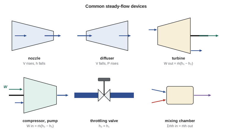
Nozzles and diffusers
A nozzle increases the velocity of a fluid at the expense of its pressure; a diffuser does the reverse. For subsonic flow a nozzle narrows in the flow direction and a diffuser widens. Neither involves work, and the fluid passes through so quickly that heat transfer is usually negligible. Potential energy changes are negligible. The kinetic energy change is the whole point, so it must be kept. The energy equation becomes
so any increase in kinetic energy is paid for by a decrease in enthalpy. For an ideal gas with constant specific heats, \(h_1 - h_2 = c_p(T_1 - T_2)\), and the fluid cools as it accelerates. Nozzles are at the heart of steam and gas turbines, where they turn enthalpy into the high-velocity jets that drive the blades; diffusers slow the air entering a jet engine's compressor, raising its pressure.
Worked problem
A compressed-air blow-off nozzle
The air heater's cleaning lance uses compressed air at 300 kPa and 200 °C, entering the nozzle at 30 m/s. The air leaves at 380 m/s. Assuming adiabatic flow and \(c_p = 1.005\ \text{kJ/(kg·K)}\), find the exit temperature.
Show solution
- Control volume: the nozzle. Steady, adiabatic, no work, negligible \(\Delta PE\).
- \[c_p(T_1 - T_2) = \frac{V_2^2 - V_1^2}{2} = \frac{380^2 - 30^2}{2(1000)} = 71.75\ \text{kJ/kg}\]
- \(T_2 = 200 - 71.75/1.005 = 128.6\ °\text{C}\).
Answer: The air cools by about 71 °C as it speeds up. The same effect, run in reverse, explains why the air at the nose of a fast aircraft is warmer than the surrounding atmosphere.
Turbines
A turbine extracts shaft work from a fluid expanding through it. In a steam or gas turbine, the fluid passes through rows of stationary nozzles and moving blades; each nozzle accelerates the fluid, and the blades turn its momentum into torque on the shaft. Across the whole machine, kinetic energy changes are usually small compared with the enthalpy drop, potential energy changes are negligible, and heat losses are small because the machine is insulated and the steam passes through in a fraction of a second. The energy equation reduces to
Worked problem
Power from the back-pressure turbine
At full load the Northgate turbine receives 12 kg/s (95,200 lbm/h) of steam at 4 MPa and 400 °C (\(h_1 = 3214.5\ \text{kJ/kg}\), 1382.0 Btu/lbm) and exhausts it into the district main at 1 MPa and 250 °C (\(h_2 = 2943.1\ \text{kJ/kg}\), 1265.3 Btu/lbm). The casing loses about 30 kW to the turbine hall. Find the shaft power.
Show solution
- \[\dot{W}_{\text{out}} = 12(3214.5 - 2943.1) - 30 = 3257 - 30 = 3227\ \text{kW}\]
- In customary units: \(95{,}200(1382.0 - 1265.3) = 11.11 \times 10^6\ \text{Btu/h}\), or 4,366 hp, before the 30 kW (102,000 Btu/h) loss.
Answer: About 3.2 MW of shaft power; with a generator efficiency near 96 percent, the plant exports about 3.1 MW of electricity. That electricity is nearly free in energy terms: the steam leaving the turbine still carries 2,943 kJ/kg, almost all of which the buildings use. This combination of heat and power is called cogeneration, and it is the main reason district energy plants run turbines at all.
Compressors, pumps and fans
Compressors, pumps and fans increase the pressure of a fluid by doing work on it. Compressors handle gases and can produce large pressure ratios; fans handle gases with small pressure rises, mainly to move them; pumps handle liquids. The energy equation is the turbine's in reverse: \(\dot{W}_{\text{in}} = \dot{m}(h_2 - h_1) + \dot{Q}_{\text{out}}\). Compressors are often cooled, by water jackets or fins, because cooler gas needs less work to compress (as Lesson 2's polytropic example showed), so the heat term may be significant.
Worked problem
The instrument-air compressor
The compressor draws 0.12 kg/s (952 lbm/h) of air at 100 kPa and 20 °C (68 °F) and delivers it at 900 kPa and 180 °C (356 °F). Cooling fins remove 3 kW. Find the power input, with \(c_p = 1.005\ \text{kJ/(kg·K)}\).
Show solution
- \[\dot{W}_{\text{in}} = \dot{m}c_p(T_2 - T_1) + \dot{Q}_{\text{out}} = 0.12(1.005)(160) + 3 = 19.3 + 3 = 22.3\ \text{kW}\]
Answer: About 22 kW. The hot air then passes through an aftercooler, a heat exchanger that cools it to near room temperature and condenses water vapor out of it before it reaches the receiver. Almost all of the 22 kW eventually leaves as heat, which is why compressor rooms need good ventilation and why heat recovery from large compressors is often worthwhile.
For a pump handling liquid water, the enthalpy rise is mostly the \(v\Delta P\) term of Lesson 5, since the temperature barely changes. The ideal pump work per unit mass is therefore \(w = v(P_2 - P_1)\), and a real pump needs more because of friction and leakage, as measured by its efficiency.
Worked problem
The feedwater pump
Saturated water at 120 kPa from the deaerator (\(v = 0.001047\ \text{m}^3/\text{kg}\)) is pumped to 4.2 MPa at 12 kg/s. The pump is 75 percent efficient. Find the power required.
Show solution
- Ideal work: \(w_{\text{ideal}} = v\Delta P = 0.001047(4200 - 120) = 4.27\ \text{kJ/kg}\).
- Actual work: \(w = 4.27/0.75 = 5.70\ \text{kJ/kg}\). Power: \(\dot{W} = 12(5.70) = 68.3\ \text{kW}\).
Answer: About 68 kW to push all the boiler water into a 4 MPa drum, compared with 3,227 kW extracted by the turbine from the same flow. The enormous difference between compressing a liquid and expanding a vapor is the key to every steam power plant, as Lesson 12 will show.
Throttling valves
A throttling valve is any restriction that causes a significant pressure drop: a partly open valve, a porous plug, a capillary tube, an orifice. There is no work, heat transfer is negligible because the device is small and the flow is fast, and kinetic and potential energy changes are usually small. The energy equation reduces to the striking result
so a throttling valve is an isenthalpic device. Enthalpy is constant, but other properties change. For an ideal gas, whose enthalpy depends only on temperature, throttling leaves the temperature unchanged. For real gases and for steam, the temperature can rise or fall. Liquids throttled below their saturation pressure partly flash into vapor and cool sharply, which is how the expansion valve in a refrigerator produces its cold refrigerant.
Worked problem
The turbine bypass valve
When the turbine is out of service, the district main is fed through a pressure-reducing valve directly from the 4 MPa, 400 °C header. What is the steam temperature in the main? At 1 MPa: \(h = 3158.2\ \text{kJ/kg}\) at 350 °C and 3264.5 kJ/kg at 400 °C.
Show solution
- Throttling: \(h_2 = h_1 = 3214.5\ \text{kJ/kg}\) at 1 MPa.
- Interpolate: \(T_2 = 350 + 50(3214.5 - 3158.2)/(3264.5 - 3158.2) = 350 + 26.5 = 376.5\ °\text{C}\).
Answer: The steam in the main would be at 376 °C instead of 250 °C, too hot for some of the older building connections. So the bypass station includes a desuperheater, which sprays feedwater into the steam to cool it. The throttling also wastes the 271 kJ/kg the turbine would have turned into work; the energy is still there, but in a less useful form, a loss that the second law makes precise.
Worked problem
Measuring steam quality with a throttling calorimeter
To check the wetness of steam in the main, Graham draws a small sample from 1 MPa through a throttling calorimeter, which expands it to 100 kPa. A thermometer after the throttle reads 130 °C. What is the quality of the steam in the main? At 100 kPa, \(h_g = 2675.0\ \text{kJ/kg}\) at 99.6 °C and \(h = 2776.6\) at 150 °C; at 1 MPa, \(h_f = 762.5\), \(h_{fg} = 2014.6\ \text{kJ/kg}\).
Show solution
- After throttling the steam is superheated at 100 kPa and 130 °C: \(h_2 = 2675.0 + (130 - 99.6)(2776.6 - 2675.0)/(150 - 99.6) = 2736.3\ \text{kJ/kg}\).
- Throttling: \(h_1 = h_2 = 2736.3\ \text{kJ/kg}\). At 1 MPa: \(x_1 = (2736.3 - 762.5)/2014.6 = 0.980\).
Answer: The steam in the main is 98 percent dry. The method works only if the steam is dry enough to be superheated after throttling, which requires a quality above about 0.95 at these pressures; for wetter steam a separating calorimeter is used first.
Mixing chambers
A mixing chamber combines two or more streams into one. It might be a T-junction in a pipe or, as at Northgate, a large vessel such as the deaerator, where steam is injected into incoming water. There is no work, the chamber is usually well insulated, and kinetic and potential energy changes are negligible. The mass and energy balances become
Worked problem
Steam needed by the deaerator
Condensate and make-up water arrive at the deaerator at 80 °C (\(h = 335.0\ \text{kJ/kg}\)). Steam from the main at 1 MPa and 250 °C (\(h = 2943.1\)) is injected to heat the water to saturation at 120 kPa (\(h_f = 439.4\ \text{kJ/kg}\)). The deaerator delivers 12 kg/s of feedwater. How much steam does it use?
Show solution
- Let \(y\) be the fraction of the outflow supplied as steam. Mass: \(\dot{m}_s + \dot{m}_w = 12\). Energy per kilogram of outflow: \(y(2943.1) + (1 - y)(335.0) = 439.4\).
- Solve: \(y = (439.4 - 335.0)/(2943.1 - 335.0) = 104.4/2608.1 = 0.0400\). Steam flow: \(0.0400(12) = 0.480\ \text{kg/s}\).
Answer: Four percent of the plant's steam is used inside the plant to heat and deaerate its own feedwater. Mixing problems always take this form: an energy-weighted average of the inlet enthalpies gives the outlet enthalpy.
Heat exchangers
A heat exchanger transfers energy between two streams without mixing them. The simplest is a tube within a tube; the building exchangers are shell-and-tube units with steam condensing in the shell and hot water flowing through the tubes; the boilers' air heaters are plate or rotary exchangers. There is no work, and kinetic and potential energy changes are negligible. If the exchanger as a whole is well insulated, the energy lost by the hot stream equals the energy gained by the cold one:
The choice of control volume matters. Drawn around the whole exchanger, there is no heat transfer across the boundary and the equation above follows. Drawn around one stream only, the heat transfer from the other stream crosses the boundary and appears as \(\dot{Q}\), as in the hospital example of Lesson 7.
Worked problem
Water flow through the hospital heat exchanger
The hospital's exchanger transfers 1.8 MW from condensing steam to the building's hot-water loop, which enters at 60 °C and leaves at 85 °C. Find the water flow rate, with \(c = 4.18\ \text{kJ/(kg·K)}\).
Show solution
- \[\dot{m}_w = \frac{\dot{Q}}{c(T_{\text{out}} - T_{\text{in}})} = \frac{1800}{4.18(25)} = 17.2\ \text{kg/s}\]
Answer: About 17 kg/s of water on the building side, against 0.70 kg/s of steam on the district side. The 25-to-1 ratio is the same advantage of latent heat noted in Lesson 3, and it shows what converting the district system to hot water would mean for pipe sizes.
Pipe and duct flow
Pipes and ducts carry fluids from one device to another. They do no work unless a pump or fan is included in the control volume, and heat transfer may or may not be important: negligible in a short, insulated pipe, but significant in a long steam main, as Lesson 7 showed, or deliberately large in a boiler tube. Kinetic energy changes are usually small; potential energy changes matter for liquids lifted through large heights. Writing the energy balance for each section of pipe and adding the results is a standard way to find heat losses or pump power in a distribution system.
The program below collects the calculations from this lesson in one place, each reduced to its characteristic one-line energy balance.
# Steady-flow energy balances for the main devices in the plant
def lerp(x, x0, x1, y0, y1):
    return y0 + (x - x0) / (x1 - x0) * (y1 - y0)

mdot = 12.0                                   # kg/s, full-load steam flow

# Turbine: 4 MPa 400 C -> 1 MPa 250 C, heat loss 30 kW, negligible KE and PE changes
h1, h2, Qloss = 3214.5, 2943.1, 30.0
W_turb = mdot * (h1 - h2) - Qloss
print(f"turbine power: {W_turb:.0f} kW")

# Pressure-reducing valve bypassing the turbine: h constant, find T at 1 MPa
T_prv = lerp(3214.5, 3158.2, 3264.5, 350, 400)       # 1 MPa row: 350 C and 400 C
print(f"PRV outlet at 1 MPa: h = 3214.5 kJ/kg, T = {T_prv:.1f} C")

# Deaerator (mixing chamber): steam at 1 MPa 250 C + condensate at 80 C -> saturated liquid at 120 kPa
h_steam, h_cond, h_out = 2943.1, 335.0, 439.4
y = (h_out - h_cond) / (h_steam - h_cond)
print(f"deaerator: steam fraction y = {y:.4f}, steam flow {y * mdot:.3f} kg/s")

# Feedwater pump: 120 kPa saturated liquid to 4.2 MPa, pump efficiency 0.75
v, dP, eta = 0.001047, 4200 - 120, 0.75
w_ideal = v * dP
print(f"pump: ideal {w_ideal:.2f} kJ/kg, actual {w_ideal / eta:.2f} kJ/kg, power {mdot * w_ideal / eta:.1f} kW")

# Throttling calorimeter: wet steam from 1 MPa throttled to 100 kPa, measured 130 C
h_cal = lerp(130, 99.61, 150, 2675.0, 2776.6)       # 100 kPa: saturated steam and 150 C
x = (h_cal - 762.5) / 2014.6
print(f"calorimeter: h = {h_cal:.1f} kJ/kg, quality of main steam x = {x:.4f}")

# Building heat exchanger: 1.8 MW into water heated from 60 C to 85 C
m_water = 1800 / (4.18 * (85 - 60))
print(f"building loop water flow: {m_water:.2f} kg/s")

# Air nozzle: 300 kPa, 200 C, 30 m/s -> 380 m/s, adiabatic, cp = 1.005
T2 = 200 - (380**2 - 30**2) / 2 / 1000 / 1.005
print(f"nozzle exit temperature: {T2:.1f} C")turbine power: 3227 kW PRV outlet at 1 MPa: h = 3214.5 kJ/kg, T = 376.5 C deaerator: steam fraction y = 0.0400, steam flow 0.480 kg/s pump: ideal 4.27 kJ/kg, actual 5.70 kJ/kg, power 68.3 kW calorimeter: h = 2736.3 kJ/kg, quality of main steam x = 0.9797 building loop water flow: 17.22 kg/s nozzle exit temperature: 128.6 C
Common mistakes
MistakeNeglecting kinetic energy in a nozzle or diffuser.
InsteadIn nozzles and diffusers the velocity change is the purpose; keep ΔV²/2.
MistakeAssuming temperature is constant across a throttling valve for steam.
InsteadEnthalpy is constant; temperature may change for real fluids.
MistakeForgetting the heat term for a cooled compressor.
InsteadẆ_in = ṁΔh + Q̇_out when the compressor is cooled.
MistakeUsing c_pΔT for a liquid pump.
InsteadFor liquids the pump work is mainly vΔP; the temperature barely changes.
MistakeIncluding heat transfer for a whole insulated heat exchanger.
InsteadFor the whole exchanger Q̇ = 0; the heat appears only when one stream is the control volume.
Summary and key terms
- Nozzles and diffusers: h₁ + V₁²/2 = h₂ + V₂²/2.
- Turbines: Ẇ_out = ṁ(h₁ − h₂) − Q̇_out; compressors and pumps: Ẇ_in = ṁ(h₂ − h₁) + Q̇_out.
- Ideal pump work for a liquid is vΔP, very small compared with turbine work.
- Throttling valves are isenthalpic: h₂ = h₁.
- Mixing chambers: Σṁ_in h_in = ṁ_out h_out.
- Heat exchangers: the energy lost by the hot stream equals the energy gained by the cold stream.
- Back-pressure turbines in district plants produce electricity while delivering most of the steam's energy as heat.
- Nozzle
- A device that increases fluid velocity at the expense of pressure.
- Diffuser
- A device that increases fluid pressure by slowing the flow.
- Turbine
- A device that produces shaft work from an expanding fluid.
- Compressor
- A device that raises the pressure of a gas by doing work on it.
- Pump
- A device that raises the pressure of a liquid.
- Throttling valve
- A flow restriction that lowers pressure with constant enthalpy.
- Isenthalpic process
- A process at constant enthalpy.
- Mixing chamber
- A device in which two or more streams combine.
- Heat exchanger
- A device that transfers energy between two fluids without mixing them.
- Cogeneration
- The production of electricity and useful heat from the same energy source.
- Throttling calorimeter
- A device that finds the quality of wet steam by throttling it to a superheated state.
Practice problems
Work each problem on paper first, then reveal the answer to check.
Steam enters a diffuser at 300 m/s and leaves at 50 m/s. What is its enthalpy rise?
Show answer
43.75 kJ/kg.
A turbine takes 5 kg/s of steam with h₁ = 3214.5 kJ/kg and exhausts it with h₂ = 2700 kJ/kg, losing 20 kW. Find the power.
Show answer
2552.5 kW.
Water at 100 kPa is pumped to 2 MPa at 3 kg/s by a pump of 70 percent efficiency (v = 0.001043). Find the power.
Show answer
About 8.5 kW.
Steam at 1 MPa with h = 2900 kJ/kg is throttled to 100 kPa, where the table gives h = 2875.5 kJ/kg at 200 °C and 2974.5 kJ/kg at 250 °C. Estimate the outlet temperature.
Show answer
About 212 °C.
Water at 15 °C (2 kg/s) mixes with water at 80 °C (1 kg/s). Find the mixed temperature.
Show answer
About 36.7 °C.
In the program, raise the calorimeter reading to 140 °C. What quality results?
Show answer
About 0.990.
Lesson quiz · 5 questions
Score 60% or more to complete this lesson.
Create a free account to save your progress, take quizzes and earn a certificate.