
LVT-310 · Lesson 3 of 12 · 22 min
Microphones, mixers and signal flow
The first piece of AV equipment Maya wires on her own is the paging microphone for Riverside's main office: a gooseneck microphone on a desk base with a push-to-talk button, cabled to the rack in the communications room two floors up. It works on the first try, but the page sounds thin and a little noisy. Wendell shows her why: the microphone input on the mixer is set for a line-level source, the cable shield is connected at both ends to two different grounds, and the gain on the DSP has been turned up to make up for it. "Every hum, hiss and squeal in a sound system starts in the first few meters of the signal chain," he says. This lesson covers microphone types and pickup patterns, signal levels, balanced and unbalanced connections, gain structure, mixers and DSPs, and the signal flow drawings that tie it all together.
How microphones work
A microphone turns sound pressure into a small electrical signal. Two types cover nearly everything an installer meets. A dynamic microphone moves a coil attached to a diaphragm inside a magnet's field, generating a voltage the way a small generator does. Dynamic microphones are rugged, need no power and handle loud sounds well; many paging and handheld microphones are dynamic. A condenser microphone uses a very thin diaphragm as one plate of a capacitor; sound moves the diaphragm and changes the capacitance, and a small amplifier inside the microphone turns that into a signal. Condensers are more sensitive and capture high frequencies better, which suits ceiling, boundary and gooseneck microphones for speech, but they need power.
That power usually comes from the mixer as phantom power: 48 volts DC sent down both signal conductors of the microphone cable equally, with the shield as the return. Because it is the same on both signal wires, it does not disturb the audio. Phantom power is switched on per input at the mixer or DSP. It does no harm to a balanced dynamic microphone, but it should be off for inputs connected to line-level equipment or to some older and unbalanced devices. Network microphones, which lesson 7 covers, are powered by PoE instead.
Pickup patterns
Microphones differ in which directions they hear. An omnidirectional microphone picks up equally from all around; it suits a microphone in the middle of a table where people sit on every side, but it also picks up room noise and loudspeaker sound from every direction. A cardioid microphone, named for its heart-shaped pattern, picks up mainly from the front and rejects sound from the rear; it is the usual choice for lecterns, paging consoles and handhelds. Supercardioid and hypercardioid patterns are narrower at the front with a small rear lobe. Beamforming ceiling microphones, common in meeting rooms, use arrays of small capsules and processing to form several narrow pickup lobes aimed at the seats, which lesson 10 covers.
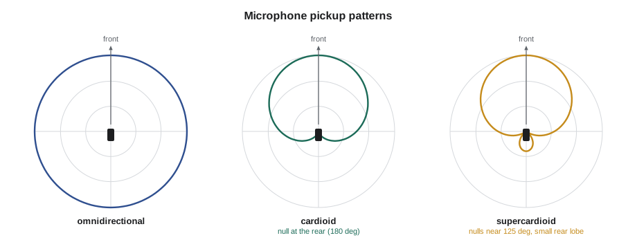
Pickup pattern matters most for feedback. Feedback is the howl that happens when a loudspeaker's sound re-enters a microphone, is amplified again, and builds up at the frequency where the loop gain is highest. A directional microphone aimed at the talker and away from the loudspeakers, loudspeakers aimed at the audience and away from the microphone, and a short distance from mouth to microphone all increase the gain available before feedback. Distance matters a lot: halving the talker's distance to the microphone raises their level at the microphone by about 6 dB, which is 6 dB more gain the system can use before it howls.
Signal levels
Audio signals travel at very different levels at different points in a system, and connecting the wrong level to an input is the first cause of poor sound. Microphone level is tiny, a few millivolts, and needs a preamplifier with high gain. Line level is the standard level between equipment: professional gear works at about +4 dBu, about 1.23 volts, and consumer gear at about −10 dBV, about 0.32 volts. Speaker level is the output of a power amplifier: tens of volts and several amperes for low-impedance loudspeakers, or up to 70 or 100 volts on distributed lines. Lesson 4 covers speaker level.
| Signal | Typical level | Example sources | Connects to |
|---|---|---|---|
| Microphone | about 1 to 10 mV | Dynamic or condenser microphone | Mic input with preamp gain |
| Consumer line | −10 dBV, about 0.32 V | Media player, laptop headphone out | Line input set for −10 |
| Professional line | +4 dBu, about 1.23 V | Mixer and DSP outputs | Line input set for +4 |
| Speaker level | Tens of volts | Amplifier output | Loudspeakers only |
The units look confusing but follow the same pattern as SPL: dBu is relative to 0.775 volts, and dBV is relative to 1 volt. Plugging a line-level source into a microphone input overloads the preamplifier and distorts; plugging a microphone into a line input leaves the signal far too weak, so someone turns up the gain later in the chain and raises the noise with it. The office paging microphone at Riverside had the second problem.
# Convert between audio level units and check a connection
import math
def dbu_to_v(dbu): return 0.775 * 10 ** (dbu / 20)
def dbv_to_v(dbv): return 1.0 * 10 ** (dbv / 20)
def v_to_dbu(v): return 20 * math.log10(v / 0.775)
print(f"+4 dBu  = {dbu_to_v(4):.3f} V")
print(f"-10 dBV = {dbv_to_v(-10):.3f} V = {v_to_dbu(dbv_to_v(-10)):.1f} dBu")
mic_mv = 5.0
print(f"A 5 mV microphone signal is {v_to_dbu(mic_mv / 1000):.1f} dBu")
gap = 4 - v_to_dbu(mic_mv / 1000)
print(f"Gain needed to bring it to +4 dBu line level: about {gap:.0f} dB")+4 dBu = 1.228 V -10 dBV = 0.316 V = -7.8 dBu A 5 mV microphone signal is -43.8 dBu Gain needed to bring it to +4 dBu line level: about 48 dB
About 50 dB of gain is needed to bring a speech microphone up to line level, which is what a microphone preamplifier provides. If that gain is not applied at the preamplifier, where the signal is cleanest, it ends up being applied later, where it amplifies every bit of noise picked up along the way.
Balanced and unbalanced connections
A balanced connection uses two signal conductors and a shield. The signal is carried on the two conductors in opposite polarity, and the receiving input subtracts one from the other. Hum or interference picked up along the cable appears equally on both conductors, so the subtraction cancels it, while the signal, which is opposite on each, adds. This is called common-mode rejection, and it is why professional audio uses balanced lines for anything longer than a few meters. Microphone cables, XLR connectors and the three-pin Euroblock, or Phoenix, terminals on most installed equipment are balanced.
An unbalanced connection uses one signal conductor and a shield that also carries the return. It has no protection against interference and suits only short connections between consumer devices, such as a media player and a nearby input. Where an unbalanced source must reach a balanced input over any distance, a balancing transformer or an active converter is used at the source end. On Euroblock terminals, the pins are usually marked plus, minus and ground; for a balanced connection both signal pins are used, and getting plus and minus swapped inverts the polarity, which can cause cancellation when two microphones or speakers are combined.
Grounding and shields cause most hum. The standard practice for installed audio is to connect cable shields at one end only where equipment is in different racks or rooms on different power circuits, usually at the receiving end or as the manufacturer's manual directs, and to keep all the AV equipment in a rack on the same power circuit and ground. A ground loop, which happens when two pieces of equipment are connected both by the shield and through separate building grounds, lets a small current flow in the shield and adds a 60 Hz hum and its harmonics. Isolation transformers break the loop where it cannot be avoided. Lifting the safety ground on equipment power cords is never the fix.
Mixers and DSPs
A mixer combines several inputs into one or more outputs, with a level control for each. Older paging systems used a small mixer amplifier that did everything in one box: microphone and music inputs, tone controls, priority muting and a power amplifier. Most installed systems now use a digital signal processor, a DSP, a rack unit with microphone and line inputs, outputs and a processing engine configured from a laptop. Inside the DSP, the designer or programmer builds the system from software blocks: input gain, high-pass filters to remove rumble, equalizers, automatic gain control, feedback suppression, compressors and limiters, mixers, matrix routers, delays and output levels.
A DSP can do in software what used to need a rack full of hardware, and it can be changed without rewiring. It can also hide mistakes: a programmer can make up for a wrongly set preamplifier with gain three blocks later, and the system will appear to work until it is examined. Cobalt Line's practice is that the installer checks the physical connections and the input settings, the programmer builds the processing from the design, and both check gain structure together at commissioning.
Gain structure
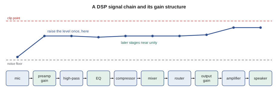
Gain structure means setting the level at each stage so the signal stays well above the noise floor and well below the clipping point everywhere along the chain. The rule is to set the gain at the first stage, the microphone preamplifier, so that normal speech reaches the design's nominal level, often around 0 dBFS minus 18 to 20 dB on a digital meter, with loud speech still leaving headroom below clipping. Every later stage should then be set close to unity, passing the signal on at about the same level, and the final level in the room set at the amplifier or the DSP's output stage. A chain built this way has the least noise and the most headroom.
Digital equipment uses dBFS, decibels relative to full scale: 0 dBFS is the largest value the converter can represent, and every signal is a negative number below it. Nothing passes above 0 dBFS; trying to produces harsh clipping. Analog and digital levels meet at the converters, where the DSP's setup states which analog level corresponds to which dBFS value.
# Check a gain structure: levels through each stage, against noise and clip points
stages = [  # name, gain dB, noise floor at stage output dBu, clip point dBu
    ("mic preamp",  48, -80, 24),
    ("high-pass",    0, -95, 24),
    ("equalizer",   -2, -95, 24),
    ("compressor",   0, -95, 24),
    ("mixer",        0, -95, 24),
    ("output gain",  2, -90, 24),
]
def run(start_dbu, name):
    level = start_dbu
    print(name)
    for st, g, noise, clip in stages:
        level += g
        flag = "CLIP" if level > clip else ("near noise" if level - noise < 40 else "ok")
        print(f"  {st:12s} {level:6.1f} dBu  headroom {clip - level:5.1f} dB  above noise {level - noise:5.1f} dB  {flag}")
run(-46, "Normal speech, gain set at the preamp:")
stages[0] = ("mic preamp", 28, -80, 24); stages[5] = ("output gain", 22, -90, 24)
run(-46, "Same speech, preamp too low and made up at the output:")Normal speech, gain set at the preamp: mic preamp 2.0 dBu headroom 22.0 dB above noise 82.0 dB ok high-pass 2.0 dBu headroom 22.0 dB above noise 97.0 dB ok equalizer 0.0 dBu headroom 24.0 dB above noise 95.0 dB ok compressor 0.0 dBu headroom 24.0 dB above noise 95.0 dB ok mixer 0.0 dBu headroom 24.0 dB above noise 95.0 dB ok output gain 2.0 dBu headroom 22.0 dB above noise 92.0 dB ok Same speech, preamp too low and made up at the output: mic preamp -18.0 dBu headroom 42.0 dB above noise 62.0 dB ok high-pass -18.0 dBu headroom 42.0 dB above noise 77.0 dB ok equalizer -20.0 dBu headroom 44.0 dB above noise 75.0 dB ok compressor -20.0 dBu headroom 44.0 dB above noise 75.0 dB ok mixer -20.0 dBu headroom 44.0 dB above noise 75.0 dB ok output gain 2.0 dBu headroom 22.0 dB above noise 92.0 dB ok
The second run shows the problem Wendell found at Riverside: with the preamplifier 20 dB too low, the signal through the middle of the chain sits 20 dB closer to the processing noise, and the extra 20 dB of output gain lifts that noise along with the voice. The page leaves the DSP at the same level as before, but about 75 dB above the noise instead of about 92: some 17 to 20 dB noisier, which is easily heard as hiss in a quiet room.
Signal flow drawings
Every AV design includes signal flow drawings, also called line diagrams or schematic diagrams. They show each device as a block with its inputs and outputs, each cable as a line with its identifier and type, and where each cable runs. The installer uses them to pull and label cable, terminate connectors, connect the rack, and later troubleshoot. Cobalt Line's labeling follows the design's scheme: each cable carries a number that appears on the drawing, the cable schedule and the labels at both ends, and each connector panel in the rack is labeled with what lands on it. When the installer makes a change in the field, such as using a spare cable because one was damaged, the change is marked on the drawing that day so the as-built record is correct at handover.
Worked problem
Hum in the office page
After Maya moves the Riverside office paging microphone to a microphone-level input with phantom power and sets the preamp gain correctly, the page is clean, but a low hum appears when the music source in the office is also connected. The music player is plugged into the office wall outlet and connects to the rack, two floors up, through a long unbalanced cable to a line input. What is happening and how should it be fixed?
Show solution
- The music player is grounded through the office outlet, and the rack is grounded through its own circuit; the unbalanced cable's shield joins the two grounds, forming a ground loop.
- Current in the shield appears as hum, and an unbalanced line has no common-mode rejection to remove it.
- The fix is to convert the music player's output to a balanced signal at the office end with a line-level balancing transformer or an active converter, and run it to the rack on a balanced pair.
- Lifting the player's ground pin is not acceptable; it creates a shock hazard.
Answer: With a balancing transformer at the office end and the shield connected only at the rack, the hum disappears and the music level is correct on a +4 dBu input.
Common mistakes
MistakeConnecting a microphone to a line-level input.
InsteadUse a microphone input with the right preamp gain and phantom power where needed.
MistakeTurning up gain late in the chain to make up for low preamp gain.
InsteadSet gain at the preamp, then run later stages near unity.
MistakeRunning long unbalanced cables between rooms.
InsteadUse balanced connections, converting unbalanced sources at the source end.
MistakeLifting a safety ground to cure hum.
InsteadFind the ground loop and break it with correct shield practice or isolation transformers.
MistakeSwapping plus and minus on a Euroblock.
InsteadKeep polarity consistent and check it when combining microphones or speakers.
Summary and key terms
- Dynamic microphones are rugged and unpowered; condensers are more sensitive and need phantom power.
- Omnidirectional microphones hear all around; cardioid and narrower patterns reject sound from the rear.
- Feedback is reduced by directional microphones, speaker placement and short talker distance.
- Microphone, line and speaker levels differ greatly; +4 dBu professional line is about 1.23 V.
- Balanced lines cancel interference by common-mode rejection; unbalanced lines suit only short runs.
- Most hum is a ground loop, fixed with shield practice, balanced lines or isolation transformers.
- DSPs replace racks of hardware with configurable processing blocks.
- Good gain structure sets gain at the preamp and keeps later stages near unity.
- Phantom power
- 48 V DC sent equally on both signal conductors of a microphone cable to power condenser microphones.
- Cardioid
- A microphone pickup pattern that hears mainly from the front.
- Balanced line
- A two-conductor shielded connection in which interference cancels at the receiver.
- Ground loop
- Two ground paths between equipment that let current flow in a shield and cause hum.
- Gain structure
- The setting of levels at each stage to keep the signal above noise and below clipping.
- dBFS
- Decibels relative to full scale in a digital system; 0 dBFS is the maximum.
- Euroblock
- A pluggable screw terminal block used for balanced audio on installed equipment.
Practice problems
Work each problem on paper first, then reveal the answer to check.
Which microphone type needs phantom power?
Show answer
A condenser microphone, unless it has its own power source.
How much gain lifts a 5 mV microphone to +4 dBu?
Show answer
About 50 dB.
What does a balanced input do with noise that appears on both conductors?
Show answer
It cancels it by subtraction.
Where should gain be set first in a signal chain?
Show answer
At the microphone preamplifier.
Lesson quiz · 5 questions
Score 60% or more to complete this lesson.
Create a free account to save your progress, take quizzes and earn a certificate.