
LVT-310 · Lesson 11 of 12 · 22 min
Control systems, testing and tuning
Two weeks before Riverside's opening, the AV equipment is installed, every cable is tested and every device answers on the network. None of that means the systems are finished. The classroom touch panels still need their programs loaded and tested; the gym's sound has not been tuned and rings like a bell; the racks have been running for days and nobody has checked how hot they get. Wendell calls this stage "making it work for people", and it takes as long as installing. This lesson covers AV control systems and how they are programmed and tested, equipment racks, power and heat, system testing with pink noise and a real-time analyzer, equalization and delay, level and coverage measurements, troubleshooting by following the signal, and the documentation that hands a system over.
What an AV control system does
A control system turns many devices into one system a person can use. Behind a classroom's single "start class" button, the control processor turns on the display, selects the teacher's input, unmutes the classroom microphone, sets the volume, and lowers the projector screen if there is one. Behind "end class", it does the reverse and starts a timer to turn everything off if the teacher forgets. The processor talks to each device in that device's language: IP commands over the network, RS-232 serial, infrared for consumer equipment, relays and contact closures for screens, blinds and lifts, and logic inputs from things like the fire alarm mute and the lockdown button.
User interfaces range from wall keypads with a few buttons, common in classrooms, to table touch panels in boardrooms and meeting rooms, and web pages or apps for facilities staff. The room system's own touch controller often doubles as the AV interface in meeting rooms. Behind them, the control program, written by a programmer using the manufacturer's tools, holds the logic: what each button does, what feedback each shows, schedules, and responses to events. Larger installations add an enterprise management server that monitors every room, reports faults to the help desk and can switch off every display in the building at night.
Programming and testing control
The programmer writes the control program from the design's functional description, which says in plain words what each button should do, and the room's device list with addresses and protocols. The installer's part is to make sure every controlled device is connected, addressed, set to accept control and reachable; a display that is set to sleep with its network port off cannot be woken by the control system, and a projector set to the wrong serial baud rate ignores every command. Before handover, every function on every interface is tested: each button pressed, each feedback checked, each schedule and event triggered, in every room. Schools have many identical rooms, and Cobalt Line tests a sample in detail and every room for the basic functions.
# Control test sheet for a classroom: functions and expected results, logged pass or fail
tests = [
    ("Start class", "display on, input teacher HDMI, mic unmuted, volume 50 %"),
    ("Source: document camera", "display input changes within 3 s"),
    ("Volume up x5", "program volume rises 5 steps, feedback updates"),
    ("Mic mute", "classroom mic muted, button lit red"),
    ("End class", "display off, mic muted, timer cleared"),
    ("Auto off at 18:00", "all room devices off"),
    ("Fire alarm mute input", "all room audio muted, panel shows message"),
    ("Lockdown input", "display shows lockdown screen, audio follows paging"),
]
results = {"Source: document camera": "fail - input changes after 9 s (display energy setting)"}
for name, expect in tests:
    r = results.get(name, "pass")
    print(f"{name:26s} {expect:58s} {r}")
print(f"{sum(1 for n, _ in tests if n not in results)} of {len(tests)} passed")Start class display on, input teacher HDMI, mic unmuted, volume 50 % pass Source: document camera display input changes within 3 s fail - input changes after 9 s (display energy setting) Volume up x5 program volume rises 5 steps, feedback updates pass Mic mute classroom mic muted, button lit red pass End class display off, mic muted, timer cleared pass Auto off at 18:00 all room devices off pass Fire alarm mute input all room audio muted, panel shows message pass Lockdown input display shows lockdown screen, audio follows paging pass 7 of 8 passed
Equipment racks
AV racks, built and tested in the shop as lesson 1 described, hold the DSPs, amplifiers, control processor, network switch, video equipment and power distribution for a system. A good rack follows the rack elevation drawing, keeps heavy amplifiers low, leaves space for air flow and future units, separates power, speaker, audio, video and network cables on opposite sides of the rack, and labels every unit and every cable to the design's scheme. Each rack has a power distribution unit, often a networked one that the control system or monitoring service can use to reboot a frozen device, and it is fed from the circuit the design specifies, with a UPS where the system must ride through power dips or carry emergency messages.
Rack power and heat
Everything in a rack turns electrical power into heat, and a rack that runs too hot shortens the life of every unit in it and can shut amplifiers down during a long event. The heat load is the total power drawn by the equipment in operation; amplifiers draw more when they play loud, so the design uses a typical operating figure, often given by the manufacturer as power at one-eighth of full output for speech and music. One watt of power produces 3.412 BTU per hour of heat, the unit most mechanical engineers in Canada and the United States use for cooling loads. The total tells the mechanical designer how much cooling the AV room needs and tells the installer whether the rack's fans or the room's ventilation are enough.
# Rack heat load and UPS sizing for the Riverside floor 2 AV rack
units = {  # unit: watts in typical operation
    "DSP": 60, "network switch (PoE to 24 mics and panels)": 420, "control processor": 20,
    "4-channel amplifier A": 180, "4-channel amplifier B": 180, "AV-over-IP encoders x4": 60, "PDU and misc": 25,
}
total_w = sum(units.values())
btu = total_w * 3.412
print(f"Total typical load {total_w} W -> heat {btu:,.0f} BTU/h")
ups_va, pf = 3000, 0.9
print(f"UPS {ups_va} VA at power factor {pf}: {ups_va * pf:.0f} W capacity, load {total_w / (ups_va * pf):.0%}")
battery_wh, eff = 1500, 0.88
print(f"Estimated runtime at typical load: {battery_wh * eff / total_w * 60:.0f} minutes")Total typical load 945 W -> heat 3,224 BTU/h UPS 3000 VA at power factor 0.9: 2700 W capacity, load 35% Estimated runtime at typical load: 84 minutes
The PoE switch is the largest load in this rack, not the amplifiers: twenty-four ceiling microphones and touch panels draw power through it. The rack's figure, about 3,200 BTU per hour, is passed to the mechanical designer, who confirms the communications room's cooling can carry it with the network equipment already there.
Testing a sound system
Sound system testing uses a few standard tools. A test signal generator, usually built into the DSP, plays pink noise, a random signal with equal energy in each octave band, which sounds like a steady hiss and excites every frequency at once. A measurement microphone, a calibrated omnidirectional microphone, captures the result at listener positions. A real-time analyzer, RTA, shows the level in each octave or third-octave band, so the installer can see whether the system is balanced or has peaks and dips. A sound level meter measures overall level. More advanced tools measure the impulse response, which shows how sound arrives at a point over time, the reflections and the reverberation, and can calculate STI, as lesson 6 described.
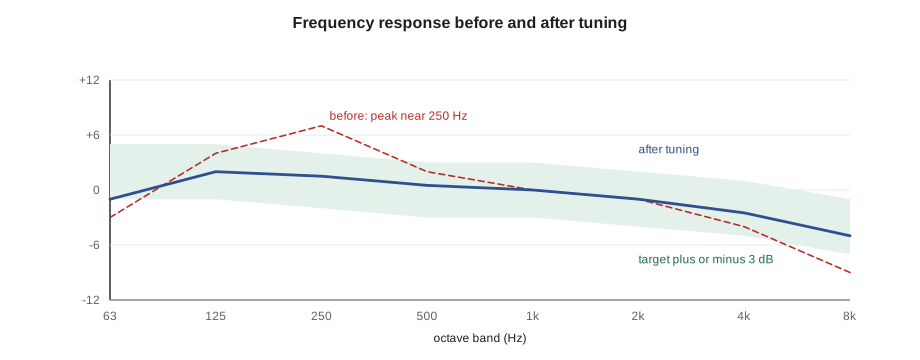
Testing proceeds in a fixed order. First, every loudspeaker is checked for sound, polarity and correct zone. Next, the system's frequency response is measured at several listener positions with pink noise, and the levels are compared across the room for coverage. Then the system is tuned: equalization, delay and levels set. Last, the result is verified by measurement and by listening with real speech and music, and the settings are saved.
Equalization, delay and level
Equalization corrects the system's frequency response for the loudspeakers and the room. Rooms add peaks at certain low frequencies and loudspeakers have their own irregularities; the installer uses parametric filters in the DSP to cut peaks, gently, rather than boosting dips, which wastes amplifier power and can cause feedback. The target is usually not flat but gently falling toward high frequencies, which sounds natural in a room. High-pass filters remove frequencies below what the speakers can reproduce, which protects them and cleans up the sound. Equalization cannot fix reverberation; a reverberant room must be treated acoustically or served with directional loudspeakers aimed at the audience.
Delay aligns loudspeakers that a listener hears from different distances. In a gym or auditorium with loudspeakers at the front and others further back, a listener near the rear speakers hears them first and the front ones later, which smears speech. Delaying the rear speakers by the time sound takes to travel the extra distance, plus a few milliseconds so the sound seems to come from the front, makes them reinforce rather than compete. Sound travels about 1,125 ft/s, so each meter of extra distance needs about 2.9 ms of delay.
# Delay for the gym's rear loudspeakers, and an EQ suggestion from an RTA measurement
SPEED = 1125                       # speed of sound, ft per second
def delay_ms(extra_distance, precedence=10):
    return extra_distance / SPEED * 1000 + precedence
print(f"Rear speakers 59 ft closer to the back bleachers: delay about {delay_ms(59):.1f} ms")
target = {63: 2, 125: 2, 250: 1, 500: 0, 1000: 0, 2000: -1, 4000: -2, 8000: -4}     # dB relative to 1 kHz
measured = {63: -3, 125: 4, 250: 7, 500: 2, 1000: 0, 2000: -1, 4000: -4, 8000: -9}
for f in target:
    err = measured[f] - target[f]
    action = "cut" if err > 2 else ("small boost or leave" if err < -2 else "ok")
print(f"{f:5d} Hz: measured {measured[f]:+3d} dB, target {target[f]:+3d} dB, error {err:+3d} -> {action}")Rear speakers 59 ft closer to the back bleachers: delay about 62.4 ms 63 Hz: measured -3 dB, target +2 dB, error -5 -> small boost or leave 125 Hz: measured +4 dB, target +2 dB, error +2 -> ok 250 Hz: measured +7 dB, target +1 dB, error +6 -> cut 500 Hz: measured +2 dB, target +0 dB, error +2 -> ok 1000 Hz: measured +0 dB, target +0 dB, error +0 -> ok 2000 Hz: measured -1 dB, target -1 dB, error +0 -> ok 4000 Hz: measured -4 dB, target -2 dB, error -2 -> ok 8000 Hz: measured -9 dB, target -4 dB, error -5 -> small boost or leave
Levels are set last. Each zone's paging and program level is set with pink noise and a sound level meter to the design's target at listener positions, then confirmed with real speech. Output limiters in the DSP are set so the system cannot be driven past what the amplifiers and loudspeakers can take, and user volume controls are given sensible maximums, so the gym's volume knob cannot be turned up into feedback.
Measuring coverage
Coverage is checked by measuring the level of pink noise at a grid of listener positions across the room and comparing the readings. AVIXA's audio coverage uniformity standard describes how such measurements are made and reported, in octave bands that matter for speech. A well-designed distributed system in a meeting room or classroom typically varies by only a few decibels across the seating area; larger variations show a gap, a dead speaker, a wrong tap or a speaker in the wrong place.
# Coverage check: pink noise readings at a grid of seats in one room, 2 kHz octave band
readings = {
    "row 1": [74.1, 74.8, 75.2, 74.6],
    "row 2": [73.9, 75.0, 74.7, 73.8],
    "row 3": [72.6, 74.2, 66.9, 73.1],
    "row 4": [72.8, 73.5, 73.9, 72.4],
}
allv = [v for row in readings.values() for v in row]
avg = sum(allv) / len(allv)
print(f"Average {avg:.1f} dB, range {max(allv) - min(allv):.1f} dB")
for row, vals in readings.items():
    for i, v in enumerate(vals, 1):
        if abs(v - avg) > 3:
print(f" {row} seat {i}: {v:.1f} dB is {v - avg:+.1f} dB from average -> check nearby speaker")Average 73.5 dB, range 8.3 dB row 3 seat 3: 66.9 dB is -6.6 dB from average -> check nearby speaker
The low seat in row 3 is below a ceiling speaker that turns out to have been tapped at 0.25 W instead of 1 W, a quarter of the power and 6 dB down. Correcting the tap brings it within a decibel of its neighbors.
Troubleshooting by following the signal
When something does not work, the fastest path to the fault is to follow the signal from source to output, block by block, as lesson 1 introduced. Is the source producing a signal, as shown on the DSP's input meter? Is it routed to the right output in the DSP? Is the output meter moving? Is the amplifier receiving it and is its channel active, not muted or in protection? Is the speaker line intact, as the impedance meter shows? For video, the same steps: is the source sending, is the extender linked, is the display on the right input, and what does the display report as the incoming format? Changing one thing at a time and recording what changed avoids creating new faults while fixing the first. Network-based systems add a step: is each device online, on the right VLAN, with its clock locked and routes intact?
Documentation and handover
An AV system is handed over with documentation that lets the owner use it and lets someone else maintain it: as-built signal flow drawings, rack elevations, cable schedules, device lists with addresses and firmware versions, DSP and control program files, display and room system settings, network requirements agreed with IT, test and tuning results, user guides for each room type, and warranty information. Passwords and administrative accounts are handed to the owner's named contact and the installer's temporary accounts removed, as for every networked system in this program. The owner's staff are trained by role: teachers on the classroom panel, office staff on paging and bells, the facilities team on the gym system and the racks, and IT on the network and management service.
Worked problem
A gym that rings
When Wendell and Maya first play pink noise through Riverside's gym system, the RTA shows a large peak around 250 Hz and the gym sounds boomy, with speech hard to follow in the back bleachers. The system has a central pair of column loudspeakers at the front and two delay speakers over the rear bleachers. The rear speakers have no delay set. What should they do, in what order?
Show solution
- Check every loudspeaker first: sound, polarity and correct zone; one of the rear columns is wired in reverse polarity, which cancels low frequencies where the two overlap. Correct it.
- Set a high-pass filter below what the columns can reproduce, then measure again at several positions.
- Cut the 250 Hz peak with a gentle parametric filter, rather than boosting the weak high frequencies.
- Set the rear speakers' delay to the extra distance from the front columns plus about 10 ms, about 62 ms for 59 ft.
Answer: After polarity, filtering, equalization and delay, speech in the rear bleachers is noticeably clearer; the remaining problem, the gym's long reverberation, is measured and handled in the capstone.
Common mistakes
MistakeHanding over a room without testing every control function.
InsteadTest every button, feedback, schedule and event, and record it.
MistakeIgnoring rack heat.
InsteadCalculate the heat load and confirm cooling with the mechanical designer.
MistakeEqualising by boosting dips.
InsteadCut peaks gently and use acoustics or directional speakers for reverberation.
MistakeLeaving delay speakers undelayed.
InsteadDelay them by the extra distance plus a few milliseconds.
MistakeChanging several settings at once while troubleshooting.
InsteadFollow the signal and change one thing at a time.
Summary and key terms
- Control systems turn many devices into one-button operation using IP, RS-232, infrared, relays and logic inputs.
- The installer makes devices reachable and controllable; every function is tested before handover.
- Racks follow the elevation, separate cable types, use networked PDUs and UPS where needed.
- Heat load in BTU/h is watts times 3.412; PoE switches can be the largest load.
- Pink noise, a measurement microphone and an RTA show frequency response and coverage.
- Equalization cuts peaks toward a gently falling target; delay aligns rear speakers at about 2.9 ms per meter plus a little.
- Coverage is checked at a grid of seats; large deviations point to gaps, dead speakers or wrong taps.
- Troubleshoot by following the signal, and hand over complete documentation, settings and training.
- Control processor
- The device that runs the control program and commands the room’s equipment.
- Functional description
- A plain-language statement of what each control function must do.
- Pink noise
- A random test signal with equal energy in each octave band.
- RTA
- Real-time analyzer: a display of level by frequency band.
- Parametric equaliser
- A filter with adjustable frequency, gain and width.
- Delay
- Holding a signal back in time to align loudspeakers at different distances.
- BTU per hour
- A unit of heat load; one watt is 3.412 BTU/h.
Practice problems
Work each problem on paper first, then reveal the answer to check.
A rack draws 1,200 W in operation. What is its heat load?
Show answer
About 4,100 BTU/h.
How much delay is needed for a speaker 40 ft closer to listeners, plus 10 ms?
Show answer
About 46 ms.
Why are peaks cut rather than dips boosted?
Show answer
Boosting wastes amplifier power and invites feedback; dips are often room effects equalization cannot fix.
What should be checked first when one zone is silent?
Show answer
The DSP input and output meters, then the amplifier channel, then the speaker line.
Lesson quiz · 5 questions
Score 60% or more to complete this lesson.
Create a free account to save your progress, take quizzes and earn a certificate.