
LVT-220 · Lesson 6 of 12 · 21 min
Power over Ethernet
Most of what Cobalt Line installs on the Brightwater floor has no power outlet nearby and does not need one. The access points in the ceiling, the cameras on the walls, the door controllers above the doors and the phones on the desks all draw their power from the switch, through the same Category 6A cable that carries their data. Power over Ethernet removes hundreds of electrical outlets and the electrician's work to install them, and lets the network team restart a frozen camera by turning its port off and on from a desk. It also makes the access switches into a large DC power system, with budgets, losses and heat that the installer has to understand. This lesson covers how PoE works, the power classes, budgets, losses in the cable and the heating of cable bundles.
How PoE works
In a PoE system, the switch, or a separate injector, is the power sourcing equipment, or PSE. The device it powers is the powered device, or PD. The PSE does not simply put voltage on every port. First it detects whether a PoE device is connected, by applying a small voltage and looking for a specific resistance, about 25 kΩ, that only a PoE device presents. A computer or a cable with no device does not show that signature and gets no power. Then the PSE classifies the device: the device presents a current at a classification voltage that says how much power it needs, and the PSE checks it has that much to give. Only then does it apply the full voltage, nominally between 44 and 57 V DC, and keep watching. If the device is unplugged, the PSE sees the current stop and turns the port off within a fraction of a second.
The detection step is why PoE is safe for ordinary network equipment: a laptop plugged into a PoE port gets data, not power. It is not safe for every device, though. Some non-standard injectors, sold as passive PoE, put voltage on the pairs without detection, and can damage equipment that was not designed for it. The crew does not use passive injectors on owner networks, and does not connect devices from non-standard systems to standard PoE ports without checking the manufacturer's instructions.
The power travels on the pairs as a common-mode voltage: both wires of a pair carry the same voltage, so the data signal, which is the difference between them, is not affected. Older PoE uses two of the four pairs; four-pair PoE uses all of them, which halves the current in each pair for the same power and reduces losses and heating.
Types and classes
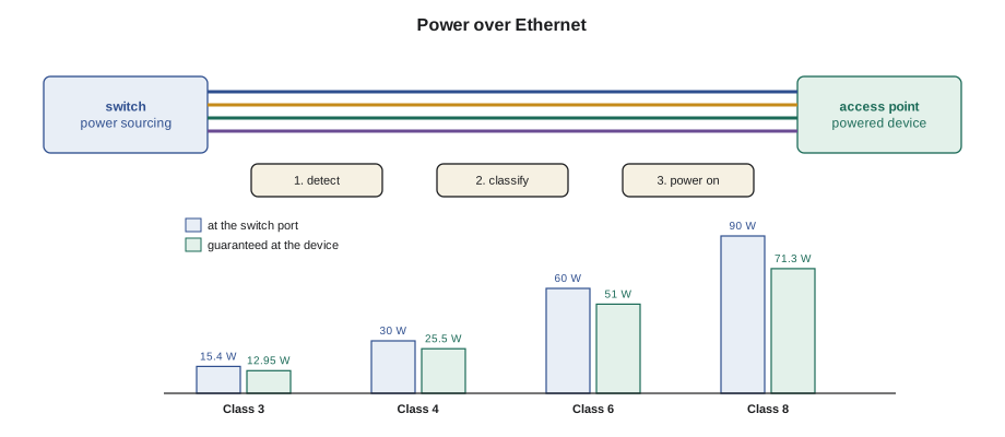
The IEEE has published PoE in three steps. IEEE 802.3af, from 2003, provides up to 15.4 W at the switch port, of which about 12.95 W is guaranteed at the device after losses in a full-length channel. IEEE 802.3at, from 2009 and often called PoE+, raises that to 30 W at the port and 25.5 W at the device. IEEE 802.3bt, from 2018, uses all four pairs for up to 60 W and 90 W at the port, with 51 W and 71.3 W guaranteed at the device. The standards call these Types 1 to 4, and within them, classes 0 to 8 describe how much a particular device asks for.
| Class | Type | Power at the switch port | Power guaranteed at the device | Pairs | Typical device |
|---|---|---|---|---|---|
| 1 | 1 | 4.0 W | 3.84 W | 2 or 4 | Sensors, small controllers |
| 2 | 1 | 7.0 W | 6.49 W | 2 or 4 | Desk phones, simple cameras |
| 3 | 1 | 15.4 W | 12.95 W | 2 or 4 | Fixed cameras, door controllers, phones with displays |
| 4 | 2 | 30 W | 25.5 W | 2 or 4 | Access points, cameras with heaters |
| 5 | 3 | 45 W | 40 W | 4 | Larger access points |
| 6 | 3 | 60 W | 51 W | 4 | Pan-tilt-zoom cameras, thin clients |
| 7 | 4 | 75 W | 62 W | 4 | Displays, high-power access points |
| 8 | 4 | 90 W | 71.3 W | 4 | Displays, lighting, heated outdoor cameras |
The difference between the two power columns is the allowance for loss in the worst-case channel: 100 m of the thinnest permitted cable at a high temperature. On a short, cool Category 6A link the loss is much smaller, but the standards guarantee only the device column, and devices are designed for it.
The switch power budget
Every PoE switch has a total power budget, the most its power supplies can deliver to all ports together. It is often much less than the number of ports times the maximum per port. A 48-port switch with ports rated for 90 W does not have 4,320 W of power; a typical budget is 740 W to 1,500 W, depending on the power supplies fitted. When the budget runs out, the switch refuses power to the next device, or, depending on its settings, turns off the lowest-priority ports to power a higher-priority one.
Switches budget power in one of two ways. Class-based allocation reserves the full class value for each device, so a Class 4 access point reserves 30 W whether it draws 12 W or 25 W. That is safe but wasteful. Allocation by actual draw, sometimes called dynamic allocation, counts what each device really draws, plus a margin, which fits more devices but can run short if every device peaks at once. Omar's switches are set to allocate by class for the cameras and door controllers, which must never lose power, and by actual draw for the phones. The network team chooses; the installer's job is to know which is in use when counting the budget.
# PoE budget for one access switch: class allocation against actual draw
CLASS_W = {1: 4.0, 2: 7.0, 3: 15.4, 4: 30.0, 5: 45.0, 6: 60.0, 7: 75.0, 8: 90.0}
budget = 740.0         # watts the switch power supplies can deliver to ports
ports = [  # (device, class, measured watts at the port)
    ("access point", 6, 24.0), ("access point", 6, 22.5), ("access point", 6, 25.1),
    ("access point", 6, 23.8), ("access point", 6, 21.9), ("access point", 6, 24.6),
    ("access point", 6, 23.0), ("camera", 3, 6.8), ("camera", 3, 7.4),
    ("camera, heater", 4, 18.2), ("door controller", 3, 9.6), ("door controller", 3, 10.1),
] + [("desk phone", 2, 3.9)] * 24
by_class = sum(CLASS_W[c] for _, c, _ in ports)
actual = sum(w for _, _, w in ports)
print(f"devices: {len(ports)}")
print(f"reserved by class: {by_class:6.1f} W of {budget:.0f} W ({100 * by_class / budget:.0f} %)")
print(f"actual draw:       {actual:6.1f} W of {budget:.0f} W ({100 * actual / budget:.0f} %)")
print(f"room for more by class: {budget - by_class:.1f} W")devices: 36 reserved by class: 679.6 W of 740 W (92 %) actual draw: 310.6 W of 740 W (42 %) room for more by class: 60.4 W
The example switch is comfortable by actual draw but more than two-thirds full by class, because the access points ask for Class 6 and draw well under half of it. Access points often ask for more power than they need on an ordinary day, because they draw more when all their radios are busy or when a USB port or second radio is in use. Omar keeps class allocation on the access points so that a busy afternoon cannot push the switch over its budget.
Power lost in the cable
Every meter of cable has resistance, and current through resistance turns into heat. The power lost in the cable is
where I is the current and R is the resistance of the loop the current flows through. In two-pair PoE, the current flows out on the two wires of one pair in parallel and back on the two wires of the other, so the loop resistance is the resistance of one wire for the full length, out and back, divided by two for the parallel wires, then doubled for the return path: in effect, one wire's resistance for the length. Four-pair PoE puts half the current on each set of pairs, and the loss falls by half for the same power. That is one reason 802.3bt uses four pairs.
# Power lost in the channel for one device: two-pair against four-pair
OHM_PER_UNIT = 0.0203          # one conductor, 23 AWG copper at 20 C, per ft
def loss(power_at_port, length, pairs=2, volts=52.0):
    current = power_at_port / volts
    loop = OHM_PER_UNIT * length          # out on one pair, back on another
    if pairs == 4:
        loop /= 2                         # two paths in parallel
    return current ** 2 * loop
for length in (100, 230, 328):
    for watts, pairs in ((30, 2), (60, 4), (90, 4)):
        lw = loss(watts, length, pairs)
print(f"{length:4d} ft, {watts} W on {pairs} pairs: loss {lw:4.1f} W ({100 * lw / watts:3.1f} %)")100 ft, 30 W on 2 pairs: loss 0.7 W (2.3 %) 100 ft, 60 W on 4 pairs: loss 1.4 W (2.3 %) 100 ft, 90 W on 4 pairs: loss 3.0 W (3.4 %) 230 ft, 30 W on 2 pairs: loss 1.6 W (5.2 %) 230 ft, 60 W on 4 pairs: loss 3.1 W (5.2 %) 230 ft, 90 W on 4 pairs: loss 7.0 W (7.8 %) 328 ft, 30 W on 2 pairs: loss 2.2 W (7.4 %) 328 ft, 60 W on 4 pairs: loss 4.4 W (7.4 %) 328 ft, 90 W on 4 pairs: loss 10.0 W (11.1 %)
On a full-length channel, a 90 W port loses several watts in the cable, which is why the device is guaranteed only 71.3 W of it. On Brightwater's short links, most under 130 ft, the loss is a few percent. The heat is spread along the cable, which brings up the second issue with PoE: what happens when many PoE cables are bundled together.
Bundles and heat
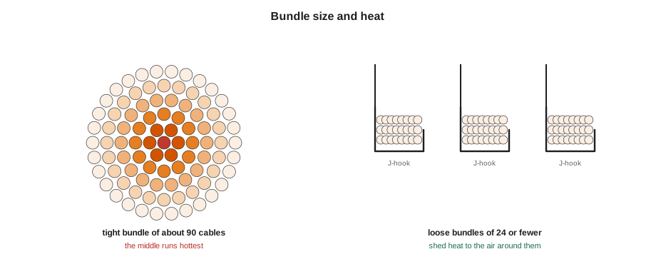
A single cable carrying PoE warms by a fraction of a degree. A bundle of a hundred cables, all carrying high-power PoE and tied tightly together in a hot ceiling, can warm by many degrees, because the cables in the middle cannot shed their heat. Hotter copper has higher resistance, so it loses more power, and the cable's insertion loss for data rises too, which shortens the distance the data can reliably travel. Above the cable's temperature rating, typically 140 °F or 167 °F, the jacket and insulation age faster.
TIA's guidance on supporting remote powering, TSB-184-A, which LVT-120 introduced, recommends Category 6A or better for new PoE installations, because its larger conductors and construction run cooler, and recommends keeping bundles to 24 cables or fewer and avoiding tight bundling where high-power PoE is used. The Canadian and US electrical codes also have rules that limit the current carried in bundles of communication and power-limited cables for the highest-power systems, and the code course, LVT-330, covers them. On the Brightwater floor, the cables to each zone box run in loose bundles under 24, on J-hooks and in open tray, which is exactly what the guidance asks for.
# Rough estimate of temperature rise in a bundle of PoE cables
# (illustrative model: rise grows with heat per unit length and with bundle size)
def rise(cables, watts_lost_per_cable, length):
    per_unit = watts_lost_per_cable / length       # heat per ft of one cable
    return 177.2 * per_unit * cables ** 0.6           # bundle factor
ambient = 95.0
for n in (12, 24, 48, 96):
    r = rise(n, watts_lost_per_cable=5.0, length=328)
print(f"{n:3d} cables, 5 W lost each: about +{r:4.1f} F, cable at {ambient + r:5.1f} F")12 cables, 5 W lost each: about +12.0 F, cable at 107.0 F 24 cables, 5 W lost each: about +18.2 F, cable at 113.2 F 48 cables, 5 W lost each: about +27.6 F, cable at 122.6 F 96 cables, 5 W lost each: about +41.8 F, cable at 136.8 F
The model is only illustrative, but it shows the shape of the problem: doubling the bundle size raises the temperature rise by about half again, and the rise is added to an ambient temperature that is already high in a ceiling. Real values depend on the cable, the installation and the airflow, and the cable manufacturer's data is the reference.
Midspans and injectors
When a switch has no PoE or not enough, power can be added between the switch and the device with a midspan, a panel with a PoE port for each switch port, or a single-port injector. Midspans are standard PoE sources, with detection and classification, and are safe to use with standard devices. They add a cord and a connection to each channel, so the channel length must still fit within 100 m, and they need their own power and their own place in the rack. On the Brightwater floor they are not needed, because the extra PoE switch was ordered in week one, but at Juniper Point the condo tower's older switches power the intercoms through a midspan in each enclosure.
Checking PoE on site
The switch's PoE status page shows, for each port, whether power is on, the class detected and the power drawn. A device that is connected but drawing nothing has not been detected: the cable may have an open pair, the device may not be PoE, or the port may have PoE turned off. A device that cycles on and off is often asking for more power than the port or the budget allows, or is on a cable with a fault that drops the voltage. A handheld PoE tester, plugged in place of the device, shows the voltage and the class the port supplies and can apply a load to confirm the port can deliver its rated power. Maya carries one for the ceiling, where a device that will not power up needs to be ruled in or out quickly.
Worked problem
A camera that keeps restarting
The outdoor camera at the Brightwater loading door, CAM-6-06, has a built-in heater and asks for Class 4. It powers up, runs for a few minutes and restarts, over and over. Its port shows Class 4 detected and power alternating between 0 and 19 W. The switch budget shows plenty of power left. What should Maya check?
Show solution
- The budget is not the problem, so look at the port and the channel.
- The camera draws more when its heater starts; a port limited below Class 4, or a voltage drop on the channel, could trip it at that moment.
- She checks the port settings with Omar: the port has a power limit of 15.4 W set from an old template, so it trips when the heater turns on.
- Omar raises the port limit to Class 4. Maya also confirms the channel length on the certification report: 102 ft, so cable loss is small.
Answer: With the port limit corrected, the camera runs steadily at about 18 W with the heater on.
Common mistakes
MistakeAssuming every port can deliver its maximum at the same time.
InsteadCheck the switch's total power budget and how it allocates.
MistakeUsing passive injectors on an owner network.
InsteadUse only standard PoE with detection and classification.
MistakeBundling many high-power PoE cables tightly.
InsteadKeep bundles small and loose, as TSB-184-A recommends.
MistakeForgetting that a midspan adds a cord to the channel.
InsteadKeep the whole channel, including midspan cords, within 100 m.
MistakeTreating a device that cycles on and off as faulty.
InsteadCheck the port power limit, the budget and the channel before replacing the device.
Summary and key terms
- PoE carries DC power on the data pairs; the switch detects, classifies and only then powers a device.
- 802.3af gives 15.4 W at the port, 802.3at 30 W and 802.3bt up to 60 W and 90 W on four pairs.
- The device is guaranteed less than the port supplies because of worst-case cable loss.
- A switch's total PoE budget is usually far less than ports times the maximum; it may allocate by class or by actual draw.
- Cable loss is I squared R; four pairs halve the loss for the same power.
- Large tight bundles of PoE cables heat up; use Category 6A, bundles of 24 or fewer and open pathways.
- The switch's PoE status and a handheld tester show whether a port is delivering power.
- PSE
- Power sourcing equipment: the switch or injector that supplies PoE.
- PD
- Powered device: the device that receives PoE.
- Detection
- The PSE's check for a PoE signature before applying power.
- Classification
- The exchange that tells the PSE how much power a device needs.
- Power budget
- The total PoE power a switch can deliver to all its ports.
- Midspan
- A PoE source placed between a non-PoE switch and the devices.
- Four-pair PoE
- PoE that uses all four pairs, as in 802.3bt.
Practice problems
Work each problem on paper first, then reveal the answer to check.
What is the power guaranteed at a Class 4 device?
Show answer
25.5 W.
A switch has a 740 W budget and reserves by class. How many Class 6 access points could it power alone?
Show answer
12, because 12 times 60 W is 720 W.
Why does four-pair PoE lose less power in the cable?
Show answer
The current is split over two paths, so each carries half and the I squared R loss halves.
A computer is plugged into a PoE port. Does it receive power?
Show answer
No; it does not present the detection signature.
Lesson quiz · 5 questions
Score 60% or more to complete this lesson.
Create a free account to save your progress, take quizzes and earn a certificate.