
LVT-210 · Lesson 10 of 12 · 20 min
Loss budgets and power meter testing (Tier 1)
Copper links are certified with a single instrument that measures dozens of parameters against a standard's limits. Fiber links are certified in two tiers. Tier 1, sometimes called basic testing, measures the loss of each strand with a calibrated light source and power meter, confirms its length and checks polarity. Tier 2, sometimes called extended testing, adds an OTDR trace of each strand, which lesson 11 covers. Most specifications require Tier 1 on every link; many backbone specifications, including Sanjay's for Riverside, require both.
This lesson covers the loss budget a link is tested against, the instruments, the reference methods that decide what the measurement includes, and the routine for testing a set of strands. It uses the St. Brendan's diverse riser, a 24-strand singlemode cable the crew installed between the hospital's two equipment rooms by a second route, and the Riverside campus link, which the capstone completes.
The loss budget
A link's loss budget is the most loss it may have and still pass. TIA-568.3 sets a generic budget built from allowances for each part of the link: an allowance per kilometer of fiber, an allowance per mated connector pair, and an allowance per splice. The designer, or the tester's limit setting, adds them up for the link as installed. Some specifications use an application limit instead, set by the equipment the link will carry, or a manufacturer's warranty limit. Whatever limit is chosen, it is set before testing and written into the test plan.
Here α is the fiber's attenuation allowance in dB per kilometer, L is the length in kilometers, N_c is the number of mated connector pairs in the link and N_s the number of splices. The usual allowances are 3.5 dB/km at 850 nm and 1.5 dB/km at 1300 nm for multimode, and 1.0 dB/km for inside plant and 0.5 dB/km for outside plant singlemode at 1310 nm and 1550 nm. A permanent link between two panels has two mated connector pairs, one at each panel, where the test cords connect.
# TIA-568.3 style loss budget for the season's links
ALLOW = {("MM", 850): 3.5, ("MM", 1300): 1.5, ("SM-ISP", 1310): 1.0, ("SM-ISP", 1550): 1.0,
         ("SM-OSP", 1310): 0.5, ("SM-OSP", 1550): 0.5}
CONN, SPLICE = 0.75, 0.3
links = [  # name, type, length (ft), connector pairs, splices
    ("Riverside OS2", "SM-OSP", 1050, 2, 2),
    ("Riverside OM4", "MM", 1050, 2, 2),
    ("St. Brendan's riser", "SM-ISP", 610, 2, 2),
    ("Kellerman backbone", "SM-ISP", 157, 2, 0),
]
TOKM = 0.0003048
for name, ftype, length, nc, ns in links:
    km = length * TOKM
    waves = (850, 1300) if ftype == "MM" else (1310, 1550)
    budgets = [ALLOW[(ftype, w)] * km + CONN * nc + SPLICE * ns for w in waves]
print(f"{name:20s} {length:5} ft: limit {budgets[0]:.2f} dB at {waves[0]} nm, {budgets[1]:.2f} dB at {waves[1]} nm")Riverside OS2 1050 ft: limit 2.26 dB at 1310 nm, 2.26 dB at 1550 nm Riverside OM4 1050 ft: limit 3.22 dB at 850 nm, 2.58 dB at 1300 nm St. Brendan's riser 610 ft: limit 2.29 dB at 1310 nm, 2.29 dB at 1550 nm Kellerman backbone 157 ft: limit 1.55 dB at 1310 nm, 1.55 dB at 1550 nm
For short links, the connectors and splices dominate the budget: the Riverside OS2 link's limit is about 2.3 dB, of which only 0.16 dB is for the fiber itself. A good installation measures far below this. Hollis expects the Riverside singlemode to measure well under 1 dB, and she treats any strand that comes close to the limit as suspect even if it passes, because a link near its limit on day one has nothing left for an extra patch, a dirty connector or aging.
The instruments
An optical loss test set is a pair of instruments: a light source and a power meter, or two units that each contain both, used at opposite ends of the link. The source launches a stable light at known wavelengths: 850 and 1300 nm for multimode, usually from LEDs or encircled-flux-controlled sources, and 1310 and 1550 nm for singlemode, from lasers. The meter measures the light arriving at the far end. Certification testers like the ones Cobalt Line uses combine source and meter in each unit, test two strands at once in both directions, measure length from the round-trip time, check polarity and compare every result with the limit, saving a record for the report.
Test reference cords connect the instruments to the link. They are high-quality cords, with reference-grade connectors whose loss against each other is very low, around 0.1 dB in multimode and 0.2 dB in singlemode. They are inspected and cleaned before every test session, protected with caps between tests, and replaced when they are worn or fail a check against each other. A worn reference cord makes every link it tests look worse than it is.
Setting the reference
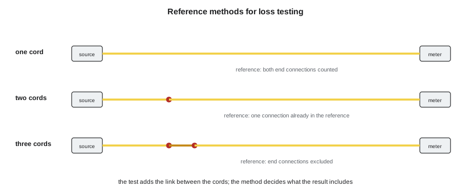
A power meter measures absolute power. To measure loss, the tester first records the power from the source through the test cords alone: this is setting the reference. The link's loss is the difference between that reference power and the power measured with the link added. What the measurement includes depends on how the reference was set, and there are three methods.
- One-cord reference: the source's cord is connected directly to the meter to set the reference. A second cord is added at the meter end for the test. The result includes both end connections of the link and the fiber between them. This is the method TIA-568.3 and most specifications require for permanent links.
- Two-cord reference: both cords are connected to each other through an adapter for the reference. The test then measures one connection fewer than the link actually has, so the result understates the loss by about one connector.
- Three-cord reference: a short third cord is placed between the two for the reference, and replaced by the link for the test. The result excludes both end connections. It is used where the instruments' ports do not allow the one-cord method, or for links that end in equipment-style connectors.
# Effect of the reference method on the same strand
fiber = 0.07         # dB, the strand's fiber attenuation
ends = [0.18, 0.22]     # dB, the link's two end connections
splices = [0.03, 0.02]  # dB
cord_joint = 0.10       # dB, the reference-grade joint between two test cords
true_link = fiber + sum(ends) + sum(splices)
one_cord = true_link
two_cord = true_link - cord_joint          # the reference already contained one joint
three_cord = fiber + sum(splices) + 2 * cord_joint - 2 * cord_joint
print(f"actual link loss:          {true_link:.2f} dB")
print(f"one-cord reference result: {one_cord:.2f} dB (both ends included)")
print(f"two-cord reference result: {two_cord:.2f} dB (about one connection too low)")
print(f"three-cord reference: {three_cord:.2f} dB (end connections excluded)")actual link loss: 0.52 dB one-cord reference result: 0.52 dB (both ends included) two-cord reference result: 0.42 dB (about one connection too low) three-cord reference: 0.12 dB (end connections excluded)
The same strand gives three different answers. That is why the reference method is written in the test plan, set in the tester and recorded with every result. A report that does not say which method was used cannot be compared with the limit. The one-cord method gives the most complete answer, and Hollis uses it for every link this season.
Encircled flux for multimode
Multimode loss depends on how the light is launched. A source that fills the outer parts of the core puts light into high-order modes, which are lost more easily at connectors and bends, so the measured loss is higher. A source that launches only into the center measures less. Different testers could therefore give different results for the same link. Encircled flux is the standard that fixes this: it specifies how the launched power must be distributed across the core, so that every compliant source gives the same result. It is defined in IEC 61280-4-1 and adopted in the TIA test standards, and most specifications for multimode require it.
In practice, the crew meets encircled flux in two ways. Their certification tester's multimode source is built to meet it with the manufacturer's matching test cords, which must be the right type and length. Older sources need a separate encircled flux conditioner, a device inserted at the source end. On the Riverside OM4, the tester's settings must show the encircled flux cords in use, and Hollis checks the cord serial numbers against the tester's setup before testing.
Testing a set of strands
Tier 1 testing follows a routine. At the start of the session, the reference cords are inspected and cleaned, the instruments warmed up for the time their manual gives, and the reference set at both wavelengths. The tester checks the reference cords against each other, and any cord that fails is replaced before the reference is reset. Then each strand pair is tested: inspect and clean the panel ports, connect, run the test, check the result and polarity, and save it under the strand's identifier. The reference is checked again at the end of the session, or every few hours, by reconnecting the cords; if it has drifted, the results since the last check are retested.
Most certification testers measure each strand in both directions and at both wavelengths. For loss, the two directions should agree closely; a large difference points to a dirty or damaged connector at one end, because a connection can lose more light in one direction than the other when one face is damaged. The difference between wavelengths, as lesson 1 explained, points to bends: in singlemode, a strand with noticeably more loss at 1550 nm than at 1310 nm has a tight bend somewhere.
# Checking a set of St. Brendan's riser results against the limit and for warning signs
LIMIT = {1310: 2.29, 1550: 2.29}       # dB, from the budget
results = {  # strand: (1310 A-to-B, 1310 B-to-A, 1550 A-to-B, 1550 B-to-A), dB
    "SB-R2-01": (0.52, 0.55, 0.49, 0.53),
    "SB-R2-02": (0.58, 0.56, 0.55, 0.57),
    "SB-R2-07": (0.61, 1.12, 0.60, 1.10),
    "SB-R2-11": (0.66, 0.64, 1.31, 1.33),
    "SB-R2-12": (0.50, 0.51, 0.47, 0.49),
}
for s, (a13, b13, a15, b15) in results.items():
    worst = max(a13, b13, a15, b15)
    status = "PASS" if worst <= LIMIT[1310] else "FAIL"
    notes = []
    if abs(a13 - b13) > 0.3 or abs(a15 - b15) > 0.3:
        notes.append("directions disagree: inspect the end connections")
    if (a15 + b15) / 2 - (a13 + b13) / 2 > 0.3:
        notes.append("more loss at 1550 nm: look for a bend")
    margin = LIMIT[1310] - worst
print(f"{s}: worst {worst:.2f} dB, margin {margin:.2f} dB, {status}; {'; '.join(notes) or 'no concerns'}")SB-R2-01: worst 0.55 dB, margin 1.74 dB, PASS; no concerns SB-R2-02: worst 0.58 dB, margin 1.71 dB, PASS; no concerns SB-R2-07: worst 1.12 dB, margin 1.17 dB, PASS; directions disagree: inspect the end connections SB-R2-11: worst 1.33 dB, margin 0.96 dB, PASS; more loss at 1550 nm: look for a bend SB-R2-12: worst 0.51 dB, margin 1.78 dB, PASS; no concerns
Every strand on the St. Brendan's riser passes, with margins of about a decibel or more. But two results deserve a second look. Strand 07 measures half a decibel more in one direction than the other, which usually means a damaged or dirty connection at one end; inspection finds a pit on the pigtail in the second equipment room, and the pigtail is replaced. Strand 11 has twice the loss at 1550 nm that it has at 1310 nm, the signature of a bend. Hollis finds it in the enclosure, where a pigtail had been pushed into a tight loop behind the adapter panel when the lid was closed. Both passed; both were fixed anyway.
The report
The test report for each link lists the strand identifier, the date, the operator, the tester and its calibration date, the reference method, the test cords, the limit used, the wavelengths, the loss in each direction, the margin, the length and the polarity result. Certification testers produce this automatically. The crew's job is to make sure the identifiers match the labels and the records, the same cross-check LVT-130 described for copper, and that every strand in every cable has a result. A cable with 24 strands has 24 results, including the strands no one is using yet.
Worked problem
Is the reference still good?
At the end of the St. Brendan's session, Teo reconnects the reference cords and the tester shows the reference has changed by 0.04 dB at 1310 nm and 0.22 dB at 1550 nm. The test plan allows a change of 0.1 dB. What should he do?
Show solution
- The 1310 nm reference is within the allowed change.
- The 1550 nm reference has changed by more than allowed, so results at 1550 nm since the last check cannot be trusted.
- A change at the longer wavelength only suggests a cord that has been bent or pinched, not a dirty connector.
- Inspect and clean the cords, check them for bends or damage, reset the reference and retest the strands since the last good check at 1550 nm.
Answer: Teo finds the source cord caught under the tester's case, frees it, resets the reference and retests the last eight strands.
Common mistakes
MistakeTesting without recording the reference method.
InsteadSet the method in the test plan and the tester, and report it with every result.
MistakeUsing a two-cord reference for a permanent link that the specification says to test with one cord.
InsteadFollow the specified method; two-cord results understate the loss.
MistakeTesting multimode without encircled flux compliant cords.
InsteadUse the source and cords the tester's setup specifies.
MistakeIgnoring a large difference between directions because the link passed.
InsteadInspect the end connections; one is probably dirty or damaged.
MistakeSkipping the end-of-session reference check.
InsteadRecheck the reference and retest any results since a drift.
Summary and key terms
- Tier 1 testing measures loss, length and polarity with a light source and power meter; Tier 2 adds an OTDR trace.
- A link's budget adds allowances for fiber length, mated connector pairs (0.75 dB each) and splices (0.3 dB each).
- Test reference cords use reference-grade connectors and must be kept clean and checked.
- The one-cord reference includes both end connections and is the method most specifications require.
- Encircled flux standardizes multimode launch conditions so results agree between testers.
- Differences between directions point to end connections; extra loss at longer wavelengths points to bends.
- Every strand is tested and reported with the method, limit, cords and margin.
- Tier 1 testing
- Loss, length and polarity testing with a light source and power meter.
- Loss budget
- The maximum loss a link may have and still pass.
- Test reference cord
- A high-quality cord with reference-grade connectors used to connect test instruments.
- One-cord reference
- A reference set with one cord, so the test includes both end connections of the link.
- Encircled flux
- A standard specification of how multimode test light is distributed across the core.
- Margin
- The difference between the limit and the measured loss.
Practice problems
Work each problem on paper first, then reveal the answer to check.
A singlemode inside plant link is 820 ft with 2 connector pairs and no splices. What is its budget?
Show answer
0.25 × 1.0 + 2 × 0.75 = 1.75 dB (820 ft is 0.25 km).
Which reference method understates loss by about one connection?
Show answer
The two-cord method.
A strand measures 0.4 dB at 1310 nm and 1.1 dB at 1550 nm. What do you look for?
Show answer
A tight bend in the cable or the enclosure.
Why is encircled flux used for multimode?
Show answer
So different testers and sources give the same result for the same link.
Lesson quiz · 5 questions
Score 60% or more to complete this lesson.
Create a free account to save your progress, take quizzes and earn a certificate.