
LVT-120 · Lesson 8 of 12 · 21 min
Optical fiber in the structured cabling system
Optical fiber carries almost every backbone in a modern building and campus, and a growing share of horizontal cabling in some designs. It carries light instead of electricity, so it is immune to electrical interference, carries no current between buildings, and reaches distances and speeds that copper cannot. This lesson places fiber within the structured cabling model: how it works, the fiber types and cable constructions, the connectors and panels, polarity and the loss budgets that the standards set. Installing, splicing and testing fiber are the subjects of LVT-210, which builds on this overview.
How optical fiber works
An optical fiber is a strand of very pure glass, about the thickness of a human hair. It has two layers: a central core, through which the light travels, and a surrounding cladding with a slightly lower refractive index. Light entering the core at a shallow enough angle strikes the boundary with the cladding and is reflected back, again and again, so it is guided along the fiber even around gentle bends. The cladding of almost all communications fiber is 125 µm in diameter, so connectors and splicing tools fit every type; what differs is the core.
The glass is protected by a plastic coating applied when the fiber is drawn, about 250 µm in diameter, and in most indoor cables by a further tight buffer of about 900 µm that makes each fiber easier to handle and terminate. A fiber's light is attenuated, weakened, slowly along its length by absorption and scattering in the glass, and faster at bends, splices and connectors. Attenuation is lowest at certain wavelengths, called windows, and fiber systems operate at those: 850 nm and 1,300 nm for multimode fiber, 1,310 nm and 1,550 nm for singlemode.
Multimode and singlemode
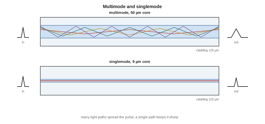
Multimode fiber has a relatively large core, 50 µm in all current types, which allows light to travel along many paths, or modes, at once. The modes arrive at slightly different times, which spreads each pulse of light and limits the bandwidth over distance. Multimode systems use inexpensive light sources, vertical-cavity lasers at 850 nm, and are used for links of up to a few hundred meters inside buildings and data centers. The ISO grades, which TIA also uses, are OM3 and OM4, the laser-optimized types used in most backbones, and OM5, which adds performance at several wavelengths for short-wave multiplexing. The older OM1 and OM2 types, with 62.5 µm and 50 µm cores, survive in older buildings but are not recommended for new work.
Singlemode fiber has a core of about 9 µm, small enough that light travels essentially in one mode. Without the spreading caused by many modes, its reach is limited by the light source and receiver, not by the fiber, over any distance found in a building or campus. Its transceivers used to cost much more than multimode ones, which kept singlemode on campus and service provider links; that difference has narrowed, and singlemode is now common in building backbones as well. The current grades are OS1a for indoor tight-buffered cable and OS2 for loose-tube and outdoor cable.
The jacket color of indoor fiber cable identifies the type by long industry convention: aqua for OM3 and OM4, with some manufacturers using a violet called erika for OM4, lime green for OM5 and yellow for singlemode. Owners may use other colors for their own purposes, so the print legend on the jacket, which states the fiber type and count, is the reliable identification.
Fiber cable construction
Fibers are packaged in cables built for where they will go.
- Tight-buffered distribution cable holds 900 µm buffered fibers, typically 2 to 144 of them, with aramid yarn for strength, in one jacket. It is the usual indoor backbone cable: flexible, easy to terminate directly, and available with riser and plenum ratings.
- Breakout cable gives each tight-buffered fiber its own subunit jacket and strength yarn, so each can be routed and handled like a small cable. It is used where fibers must branch to separate equipment.
- Loose-tube cable carries 250 µm fibers loosely in gel-filled or dry water-blocked tubes, which isolate the fibers from stretching and temperature changes. It is the standard outdoor and campus cable. Fibers from loose tubes are usually spliced to factory-made pigtails rather than terminated directly.
- Indoor/outdoor cable combines outdoor water resistance with an indoor fire rating, so a campus cable can run from one building's equipment room to another's without a transition splice at each entrance.
- Armored cable adds an interlocking aluminum or steel armor for protection against crushing and rodents. Metallic armor must be bonded where it enters a building, as Lesson 3 noted.
Ribbon cable, in which fibers are bonded side by side in flat ribbons of 12, is used where very high fiber counts must be spliced quickly, as in large data centers and service provider networks. Each ribbon is spliced in one operation.
Connectors, panels and polarity
Fiber connectors align two fiber ends so precisely that light passes from one core to the next with little loss, and they hold the ends in a ceramic or metal ferrule polished to a smooth end face. The common types in structured cabling are the LC, a small connector with a ferrule half the diameter of the SC's, used on almost all current transceivers and patch panels; the older and larger SC, still common on service provider equipment; and the MPO, which holds 12, 16 or 24 fibers in one rectangular ferrule for parallel optics and pre-terminated trunk cables in data centers. Most connectors use an ultra physical contact polish, color-coded blue on singlemode; angled physical contact connectors, with an 8 degree angled end face, are color-coded green, reflect much less light and are used in video and passive optical networks. An angled connector must never be mated to a flat one.
Fiber cables terminate in enclosures or patch panels in the telecommunications room and equipment room, where the fibers are protected, managed and presented on adapter panels, plates of mating sleeves. Many current installations use pre-terminated cassettes: a factory-made module with MPO connectors on the back and LC adapters on the front, connected by an MPO trunk cable, so that a backbone can be installed and plugged in without field termination.
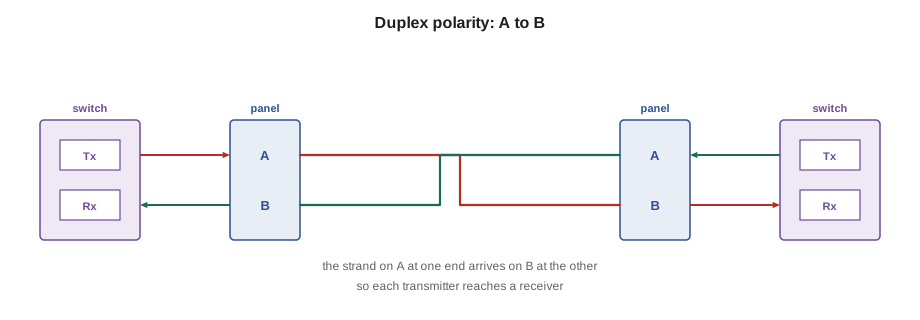
A fiber link uses two fibers, one in each direction. Polarity is the discipline of making sure that the transmitter at one end always connects to the receiver at the other. TIA-568 defines it with letters: on a duplex connection, each link is wired so that the fiber on position A at one end arrives at position B at the other, a crossover built into the cabling or the cords. For MPO trunks and cassettes, TIA-568 defines several methods, called A, B and C, which differ in where the crossover is made. The rule for a contractor is simple: use one polarity method consistently across a project, document it, and use the cords and cassettes that method requires. Mixed methods are the commonest cause of a new fiber link that tests well but does not light up.
Loss budgets
A fiber link is designed and tested against a loss budget: the maximum total attenuation allowed between the transmitter and the receiver. TIA-568.3 sets the allowances used to calculate the expected loss of an installed link: 0.75 dB for each mated connector pair, 0.3 dB for each splice, and a fiber attenuation per kilometer at each wavelength. Multimode fiber is allowed 3.5 dB per km at 850 nm and 1.5 dB per km at 1,300 nm. Singlemode fiber is allowed 1.0 dB per km for inside-plant cable and 0.5 dB per km for outside-plant cable at 1,310 and 1,550 nm. The application, such as 10GBASE-SR, also has its own maximum channel loss, and the designer checks that the link's calculated loss is below it.
Here n with subscript c is the number of mated connector pairs, n with subscript s the number of splices, L the length in kilometers and the Greek letter alpha the fiber's allowed attenuation per kilometer. The result is a maximum: a well-made link usually measures much less. LVT-210 shows how the measured loss is compared with this calculated limit.
# Calculated maximum loss of backbone fiber links (TIA-568.3 allowances)
CONN, SPLICE = 0.75, 0.3
ALPHA = {("MM", 850): 3.5, ("MM", 1300): 1.5, ("SM", 1310): 1.0, ("SM", 1550): 1.0}
links = [("ER1 to TR 3A", "MM", 0.085, 2, 0),
         ("ER1 to gym", "SM", 0.32, 2, 2),
         ("ER1 to gym", "MM", 0.32, 2, 2)]
for name, kind, km, conns, splices in links:
    for (k, wl), a in ALPHA.items():
        if k != kind:
            continue
        loss = conns * CONN + splices * SPLICE + km * a
        print(f"{name:13} {kind} at {wl} nm: {km * 1000:4.0f} m, {conns} connector pairs, "
f"{splices} splices -> {loss:.2f} dB")ER1 to TR 3A MM at 850 nm: 85 m, 2 connector pairs, 0 splices -> 1.80 dB ER1 to TR 3A MM at 1300 nm: 85 m, 2 connector pairs, 0 splices -> 1.63 dB ER1 to gym SM at 1310 nm: 320 m, 2 connector pairs, 2 splices -> 2.42 dB ER1 to gym SM at 1550 nm: 320 m, 2 connector pairs, 2 splices -> 2.42 dB ER1 to gym MM at 850 nm: 320 m, 2 connector pairs, 2 splices -> 3.22 dB ER1 to gym MM at 1300 nm: 320 m, 2 connector pairs, 2 splices -> 2.58 dB
Compared with an application's limit, these figures settle design questions quickly. The 10GBASE-SR application over OM4 allows a channel loss of roughly 2.9 dB, so the 280 ft riser link at about 1.8 dB has room to spare, while the gymnasium's 1,050 ft multimode link, with its two transition splices, comes to about 3.2 dB at 850 nm and would not be reliable. That matches the choice of singlemode for the gymnasium in Lesson 4.
Fiber beyond the backbone
Fiber also reaches beyond the backbone in some designs. Fiber to the zone runs fiber from the telecommunications room to small switches in ceiling enclosures, each serving a zone with short copper links. Passive optical LAN uses the technology of service provider fiber-to-the-home networks inside buildings: singlemode fiber from the equipment room passes through passive optical splitters to small terminals near the users, with no switches in the telecommunications rooms at all. Both reduce the number of copper cables and telecommunications rooms, at the cost of more active equipment near users. Most of Cobalt Line's work still uses copper horizontal cabling, but Maya should recognize these designs on drawings.
Fiber brings two safety rules that apply from the first day on any job, covered in detail in LVT-210. The light in communications fiber is often invisible infrared, and a laser source can damage the eye, so nobody looks into a fiber end or connector, and inspection is done with a video microscope or a scope with a filter. And the glass slivers produced when fiber is cleaved are sharp and almost invisible: they go into a marked disposal container, never onto the floor or the bench, and nobody eats or drinks where fiber is being terminated.
Worked problem
Identifying the fiber at Juniper Point
At Juniper Point, the condo tower's existing fiber backbone runs from the ground-floor equipment room to telecommunications enclosures on every fourth floor. The cable jackets are aqua, the panels have blue LC adapters, and the as-built drawings say only 12F. The property manager wants to add 10 gigabit uplinks. What should Maya determine before anyone orders optics?
Show solution
- The aqua jacket suggests OM3 or OM4 multimode, but the print legend on the jacket is the reliable source; she reads it in the equipment room and at an enclosure: 12-fiber OM3.
- She checks the length to the farthest enclosure from the drawings or the jacket's length markings: about 230 ft.
- OM3 carries 10GBASE-SR to 300 m, so the existing fiber supports 10 gigabit uplinks with SR optics.
- She notes that the blue adapters on a multimode panel are not a color standard for multimode, records the polarity method from the panel labels, and confirms how many of the 12 fibers are already in use.
Answer: The backbone is 12-fiber OM3 at about 230 ft, suitable for 10GBASE-SR uplinks; Maya records fiber type, length, polarity and spare strands for Sanjay.
Common mistakes
MistakeIdentifying fiber type by jacket color alone.
InsteadRead the print legend on the jacket for type and count.
MistakeMating an angled (green) connector with a flat-polished one.
InsteadMate APC only with APC, and UPC with UPC.
MistakeMixing polarity methods on one project.
InsteadChoose one method, document it and use matching cords and cassettes.
MistakeLooking into a connector to see whether light is present.
InsteadUse a power meter or visual fault locator correctly and inspect with a filtered scope.
MistakeSpecifying multimode for a long campus link at a future high speed.
InsteadCheck reach and loss budget at the fastest expected application; consider singlemode.
Summary and key terms
- Fiber guides light in a glass core surrounded by a 125 µm cladding, and is immune to electrical interference.
- Multimode fiber (OM3, OM4, OM5) has a 50 µm core and serves shorter links; singlemode (OS1a, OS2) has a 9 µm core and serves any building or campus distance.
- Tight-buffered cable serves indoor backbone; loose-tube cable serves outdoor and campus routes; indoor/outdoor cable avoids transition splices.
- LC is the common connector, MPO carries parallel optics and trunks, and angled and flat polishes must not be mixed.
- Polarity keeps every transmitter connected to a receiver; use one method per project.
- Loss budgets use 0.75 dB per connector pair, 0.3 dB per splice and the fiber's allowed attenuation per kilometer.
- Core
- The central part of a fiber that carries the light.
- Cladding
- The glass layer around the core, with a lower refractive index, that keeps light in the core.
- Multimode fiber
- Fiber with a 50 µm core that carries many light paths, used for shorter links.
- Singlemode fiber
- Fiber with a core of about 9 µm that carries essentially one light path over long distances.
- Loose-tube cable
- Cable with fibers carried loosely in protective tubes, used outdoors.
- MPO
- A multi-fiber connector holding 12 or more fibers in one ferrule.
- Polarity
- The arrangement that connects each transmitter to the receiver at the other end.
- Loss budget
- The maximum attenuation allowed for a fiber link or application.
Practice problems
Work each problem on paper first, then reveal the answer to check.
What are the core sizes of multimode and singlemode fiber?
Show answer
50 µm for current multimode; about 9 µm for singlemode.
What color identifies an angled physical contact connector?
Show answer
Green.
Calculate the maximum loss of a 150 m OM4 link at 850 nm with two connector pairs and no splices.
Show answer
2 × 0.75 + 0.15 × 3.5 = 1.5 + 0.525 = 2.03 dB.
What problem does polarity solve?
Show answer
It ensures the transmitter at each end is connected to the receiver at the other.
Why is indoor/outdoor cable useful on a campus?
Show answer
It can run from one building's room to another's without a transition splice at each entrance.
Lesson quiz · 5 questions
Score 60% or more to complete this lesson.
Create a free account to save your progress, take quizzes and earn a certificate.