
LVT-120 · Lesson 2 of 12 · 21 min
The structured cabling model (TIA-568 and ISO/IEC 11801)
Every structured cabling system, from a single office to a hospital campus, is built from the same small set of building blocks. The standards give those blocks names, define how they connect, and set the limits that each must meet. Once the model is clear, a set of cabling drawings becomes readable: the riser diagram shows the backbone, the floor plans show the horizontal cabling and outlets, the room elevations show the cross-connects, and every item on the drawings belongs to one block of the model. This lesson sets out that model in the language of ANSI/TIA-568 and of its international counterpart, ISO/IEC 11801, because Maya will meet both on drawings and in manufacturers' literature.
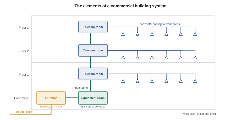
The elements of a commercial building system
ANSI/TIA-568.1, the commercial building standard, describes six elements. They are worth learning in the order a signal travels from the outside world to a desk.
- The entrance facility is where outside cabling enters the building: the service provider's cables, cables from other buildings on a campus and, for some owners, antennas. It holds the demarcation point, where the provider's responsibility ends and the owner's begins, and the protection for any metallic cables entering from outside.
- The equipment room is a central space that houses the building's main network and telephone equipment and, usually, the main cross-connect for the building or campus. It is larger and more environmentally controlled than a telecommunications room.
- Backbone cabling connects the entrance facility, the equipment room and the telecommunications rooms. Within a building it usually runs vertically in a riser; between buildings it runs underground or overhead.
- The telecommunications room is a space on each floor, or serving each area, that holds the horizontal cross-connect: the patch panels on which the horizontal cables terminate, and usually the switches that serve that floor. A small space serving a limited area, often a wall or ceiling cabinet, is called a telecommunications enclosure.
- Horizontal cabling runs from the telecommunications room to the outlets in the work areas. It is the largest part of any system by cable length and by labor, and the part most affected by the building's layout.
- The work area is where users and devices connect: the outlet, and the cords and adapters that connect equipment to it. Work area equipment itself, the computer or the telephone, is not part of the cabling system.
Cross-connects and interconnects
The places where cabling subsystems meet are called cross-connects. In a cross-connect, both sets of cable terminate on connecting hardware, such as two groups of patch panels, and short patch cords or jumpers connect them. Changing a connection means moving a patch cord; neither permanent cable is touched. In an interconnect, one set of cable terminates on a patch panel and equipment cords run directly from that panel to the network equipment. An interconnect has one fewer connection in the signal path and uses less rack space, so it is the usual arrangement in a telecommunications room where the switches are installed alongside the horizontal patch panels. A cross-connect is preferred where flexibility matters more than space, or where the equipment and the cabling belong to different groups, as in a hospital where the network team does not want cabling contractors touching its switches.
TIA-568.1 names three levels of cross-connect. The main cross-connect, in the equipment room, is the center of the star. An intermediate cross-connect is an optional second level, used on large campuses and in large buildings. The horizontal cross-connect, in each telecommunications room, is where the backbone meets the horizontal cabling. The rule that keeps the star hierarchical is simple: there may be no more than two levels of cross-connect in the backbone between the main cross-connect and any horizontal cross-connect. A signal from the main cross-connect therefore passes through at most one intermediate cross-connect before it reaches the horizontal cross-connect, and no backbone cable may run sideways from one telecommunications room to another as part of the permanent star.
The generic model: distributors and subsystems
ANSI/TIA-568.0, the generic standard that applies to all types of premises, uses more abstract names so that the same model can describe an office, a factory, a hospital or a data center. The connection points are called distributors and the cable between them cabling subsystems. Distributor C is the top of the star, Distributor B is the optional intermediate level and Distributor A is the level closest to the outlets. Cabling Subsystem 1 runs from Distributor A to the equipment outlet; Subsystem 2 runs from Distributor B to Distributor A; Subsystem 3 runs from Distributor C to Distributor B. In an office building, Distributor C is the main cross-connect, Distributor A is the horizontal cross-connect and Subsystem 1 is the horizontal cabling, so the two vocabularies describe the same system.
ISO/IEC 11801 uses a third vocabulary. Its campus distributor, building distributor and floor distributor correspond to the main, intermediate and horizontal cross-connects, and its telecommunications outlet is the work area outlet. Its campus backbone, building backbone and horizontal cabling subsystems match the TIA subsystems. ISO also classifies performance by channel classes rather than component categories: Class D, E, EA, F, FA and the 2,000 MHz Classes I and II. Lesson 6 shows how they line up with the TIA categories.
| TIA-568.1 (commercial) | TIA-568.0 (generic) | ISO/IEC 11801 |
|---|---|---|
| Main cross-connect (MC) | Distributor C | Campus distributor (CD) |
| Intermediate cross-connect (IC) | Distributor B | Building distributor (BD) |
| Horizontal cross-connect (HC) | Distributor A | Floor distributor (FD) |
| Horizontal cabling | Cabling Subsystem 1 | Horizontal cabling subsystem |
| Backbone cabling, HC to IC | Cabling Subsystem 2 | Building backbone subsystem |
| Backbone cabling, IC to MC | Cabling Subsystem 3 | Campus backbone subsystem |
| Telecommunications outlet | Equipment outlet | Telecommunications outlet (TO) |
Optional points in the horizontal
Two optional elements allow the horizontal cabling to adapt to open offices. A consolidation point is an interconnection in the horizontal cable, typically in a ceiling or floor box serving a zone of furniture. The cable from the telecommunications room to the consolidation point is permanent; the shorter cables from the consolidation point to the outlets can be replaced when the furniture is rearranged. A multi-user telecommunications outlet assembly, or MUTOA, is a group of outlets in one housing, mounted on a column or wall, from which long work area cords run directly to the devices in an open area. Both have limits on their use and on cord lengths, set out in Lesson 5.
There are also some things the model does not allow in the permanent horizontal. A horizontal link may contain at most one consolidation point, may not contain splices in twisted-pair cable, and may not contain bridged taps, the branch connections once common in telephone wiring. Splitting one four-pair cable to serve two outlets is also not permitted. Each outlet gets its own cable all the way to the telecommunications room.
Recognized media
The standards list the cable types that may be used in each subsystem, called recognized media. For horizontal cabling, TIA-568.1 recognizes four-pair balanced twisted-pair cable of 100 ohm impedance, of Category 5e or higher, and multimode or singlemode optical fiber. For backbone cabling, it also recognizes multipair twisted-pair cable for voice. Coaxial cable is covered by a separate standard, TIA-568.4, for broadband and video distribution, and is not recognized as horizontal data cabling. Category 6A is the minimum recommended for new horizontal installations that will carry Power over Ethernet or serve wireless access points, and most owner standards now require it everywhere.
Other premises standards adapt the same model to particular buildings: TIA-942 for data centers, TIA-1179 for healthcare facilities, TIA-4966 for educational buildings, TIA-570 for residential buildings, TIA-862 for building automation systems and TIA-1005 for industrial premises. Each keeps the hierarchical star and the distributor names but adds requirements suited to the building, such as outlet densities for hospital rooms or the ruggedized components of a factory floor.
Checking a design against the model
Sanjay checks every design he draws against the topology rules before he counts a single cable. The check is mechanical, so he has written a short script for it: each distributor is listed with the distributor it is cabled from, and the script walks the tree to report how many levels each telecommunications room sits below the main cross-connect and whether any room is cabled from another room at the same level.
# Check a backbone design against the hierarchical-star rules (TIA-568.1)
# each entry: distributor -> (level, cabled from)
design = {
    "MC-ER1":  ("MC", None),
    "IC-BLDGB": ("IC", "MC-ER1"),
    "HC-1A":   ("HC", "MC-ER1"),
    "HC-2A":   ("HC", "MC-ER1"),
    "HC-3A":   ("HC", "MC-ER1"),
    "HC-B1":   ("HC", "IC-BLDGB"),
    "HC-B2":   ("HC", "HC-B1"),      # proposed: room B2 fed from room B1
}
rank = {"MC": 0, "IC": 1, "HC": 2}

for name, (level, parent) in design.items():
    if parent is None:
        continue
    plevel = design[parent][0]
    hops, p = 0, name
    while design[p][1] is not None:
        p = design[p][1]; hops += 1
    ok = rank[plevel] < rank[level] and hops <= 2
    note = "ok" if ok else "NOT ALLOWED: must be cabled from a higher level"
print(f"{name:9} ({level}) fed from {parent:9} ({plevel}), {hops} backbone level(s): {note}")IC-BLDGB (IC) fed from MC-ER1 (MC), 1 backbone level(s): ok HC-1A (HC) fed from MC-ER1 (MC), 1 backbone level(s): ok HC-2A (HC) fed from MC-ER1 (MC), 1 backbone level(s): ok HC-3A (HC) fed from MC-ER1 (MC), 1 backbone level(s): ok HC-B1 (HC) fed from IC-BLDGB (IC), 2 backbone level(s): ok HC-B2 (HC) fed from HC-B1 (HC), 3 backbone level(s): NOT ALLOWED: must be cabled from a higher level
The script flags the proposal for room B2: cabling it from room B1 would create a horizontal-to-horizontal link, which breaks the star and would add a third level of cross-connect. The fix is to run B2's backbone from the intermediate cross-connect in Building B, like B1's.
Worked problem
Mapping Riverside school onto the model
Riverside's drawings show: a service provider's fiber and copper entering a room in the basement; the main network equipment and a rack of fiber panels in a room next to it; a telecommunications room on each of the three floors, numbered 1A, 2B and 3A; outlets in classrooms and offices; and, across the site, a separate gymnasium building with its own small room. Identify each element and check the topology.
Show solution
- The basement room where the service enters is the entrance facility, with the demarcation point and protection for the copper.
- The room with the main network equipment is the equipment room, holding the main cross-connect (Distributor C).
- Rooms 1A, 2B and 3A are telecommunications rooms, each with a horizontal cross-connect (Distributor A). Each should be cabled directly from the main cross-connect by backbone cable running in the riser.
- The gymnasium's room is a horizontal cross-connect in a second building. It may be cabled directly from the main cross-connect by campus backbone, which is one backbone level, or from an intermediate cross-connect, which would be two levels. Both are within the rule.
- The cabling from each room to the classroom outlets is horizontal cabling, and the classrooms are work areas.
Answer: Every space on the drawings fits one element of the model, and the backbone design stays within two levels of cross-connect.
Reading drawings with the model
On Cobalt Line's drawing sets, each element of the model has its own sheet type. The riser diagram shows the entrance facility, equipment room, backbone cables and telecommunications rooms as a schematic, without scale. Floor plans show outlets as symbols, each with a small number giving its cable count, and the pathways that reach them. Room plans and rack elevations show the cross-connects in detail, panel by panel. When Maya is unsure where something belongs, she asks which element of the model it is, and the answer tells her which sheet to look at and which rules apply.
Common mistakes
MistakeCabling one telecommunications room from another to save backbone cable.
InsteadCable each room from the main or an intermediate cross-connect; the permanent star has no lateral links.
MistakeUsing a splice or a bridged tap in a twisted-pair horizontal link.
InsteadRun each horizontal cable continuously from the panel to its outlet, with at most one consolidation point.
MistakeTreating the computer and its cord as part of the cabling system.
InsteadThe system ends at the outlet; work area equipment is outside it.
MistakeConfusing a consolidation point with a MUTOA.
InsteadA consolidation point is an interconnection in the cable; a MUTOA is a group of outlets with long cords to the devices.
MistakeMixing TIA and ISO terms on one set of drawings.
InsteadUse the project's vocabulary consistently, and translate when reading literature.
Summary and key terms
- A commercial cabling system has six elements: entrance facility, equipment room, backbone cabling, telecommunications rooms, horizontal cabling and work areas.
- Cross-connects join subsystems with patch cords between two sets of panels; interconnects connect panels directly to equipment.
- The backbone may have at most two levels of cross-connect between the main and any horizontal cross-connect.
- TIA-568.0 uses Distributors A, B and C and Cabling Subsystems 1 to 3; ISO/IEC 11801 uses campus, building and floor distributors and channel classes.
- A horizontal link may have one consolidation point and no splices, bridged taps or shared cables.
- Recognized horizontal media are four-pair 100 ohm twisted pair of Category 5e or higher and optical fiber; Category 6A is preferred for new work.
- Entrance facility
- The space where outside cabling enters the building, including the demarcation point and protection.
- Equipment room
- A central, environmentally controlled space for main equipment and the main cross-connect.
- Telecommunications room
- A space on each floor or area that holds the horizontal cross-connect and its equipment.
- Cross-connect
- A connection between two cabling subsystems made with patch cords or jumpers between two sets of terminations.
- Interconnect
- A connection in which equipment cords run directly from a patch panel to network equipment.
- Distributor
- The generic term in TIA-568.0 for a connection point in the hierarchical star (A, B or C).
- Consolidation point
- An optional interconnection in a horizontal cable that allows part of the cable to be replaced when furniture moves.
- Recognized media
- The cable types a standard permits in a given cabling subsystem.
Practice problems
Work each problem on paper first, then reveal the answer to check.
What element holds the demarcation point?
Show answer
The entrance facility.
A floor's switches plug directly into the horizontal patch panels with equipment cords. Is that a cross-connect or an interconnect?
Show answer
An interconnect.
How many levels of cross-connect may the backbone have between the main and a horizontal cross-connect?
Show answer
At most two, so a signal passes through no more than one intermediate cross-connect.
What is Distributor A in an office building, and what is its ISO name?
Show answer
The horizontal cross-connect; ISO calls it the floor distributor.
May a contractor split one four-pair cable between two outlets?
Show answer
No; each outlet needs its own cable to the telecommunications room.
Lesson quiz · 5 questions
Score 60% or more to complete this lesson.
Create a free account to save your progress, take quizzes and earn a certificate.