
LVT-120 · Lesson 7 of 12 · 21 min
Connectors, outlets and work areas
Every structured cabling channel is a chain of cable and connections, and the connections are where most of the performance is won or lost. A Category 6A cable run perfectly through the ceiling will fail if it ends on a Category 5e jack, or on the right jack with the pairs untwisted too far. This lesson covers the connecting hardware of the horizontal: the modular jack and plug, the two wiring schemes, patch panels and punch-down blocks, outlets and faceplates, and the cords that complete the channel at each end. It also covers the work area itself, where the cabling meets its users. The hands-on skills of terminating jacks and panels are taught in LVT-130; this lesson explains what the hardware is and how it is chosen.
The eight-position modular connector
The connector at the end of almost every horizontal channel is the eight-position, eight-contact modular jack and plug, commonly called RJ45. Strictly, RJ45 is an old telephone industry designation for a particular wiring of that connector, and the standards call it an eight-position modular connector, but the informal name is universal. The jack has eight spring contacts in a row, numbered 1 to 8 from left to right when viewed from the front with the latch slot down, and on the back it has insulation displacement contacts into which the cable's eight conductors are pressed. Higher-category jacks are built with small compensating circuits on their internal boards that cancel the crosstalk created inside the plug, which is why jacks are matched to a category and, on warranted systems, to the manufacturer's cable.
The plug is crimped onto stranded cords in a factory. Field-terminated plugs, used for modular plug terminated links to cameras and access points, are made for solid horizontal cable and must be the type specified for that use. Factory-made cords are preferred everywhere else, because their performance is tested and consistent.
T568A and T568B
The four pairs of a cable are identified by color: blue, orange, green and brown, each with a solid-colored conductor and a white conductor striped with that color. TIA-568 defines two ways to assign the pairs to the eight jack positions, called T568A and T568B. Both keep each pair on two positions that the equipment expects to be a pair, and both perform identically. The only difference is that the orange and green pairs swap places.
| Position | T568A | T568B | Pair (T568A / T568B) |
|---|---|---|---|
| 1 | white-green | white-orange | 3 / 2 |
| 2 | green | orange | 3 / 2 |
| 3 | white-orange | white-green | 2 / 3 |
| 4 | blue | blue | 1 / 1 |
| 5 | white-blue | white-blue | 1 / 1 |
| 6 | orange | green | 2 / 3 |
| 7 | white-brown | white-brown | 4 / 4 |
| 8 | brown | brown | 4 / 4 |
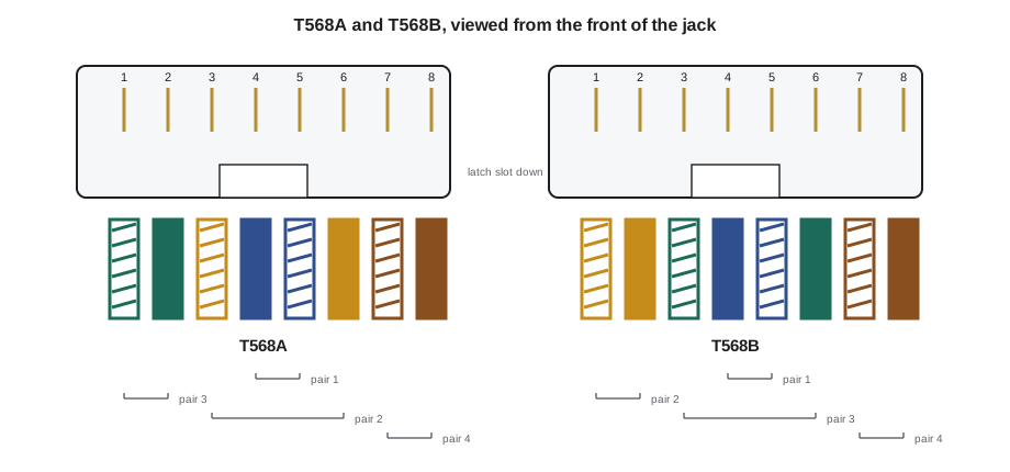
What matters is consistency. Both ends of a horizontal link must be terminated to the same scheme; a link with T568A at one end and T568B at the other is a crossed link that will fail a wiremap test. TIA-568 lists T568A as the preferred scheme, and many Canadian and US government and institutional specifications require it, while T568B is widely used in commercial work by long habit. Most jacks are printed with color codes for both schemes, which is convenient and also how mistakes happen: an installer reading the wrong row of colors terminates one end to the other scheme. Cobalt Line marks the scheme for each job on its work orders, and Dev checks the first few jacks a new apprentice terminates at both ends.
Cords are wired straight through: position 1 at one end to position 1 at the other, and so on. Crossover cords, which swapped pairs to connect two similar devices directly, are no longer needed because modern equipment detects and corrects the crossover automatically.
# Wiremap check: compare the far-end positions of a link with what each scheme expects
A = ["white-green", "green", "white-orange", "blue", "white-blue", "orange", "white-brown", "brown"]
B = ["white-orange", "orange", "white-green", "blue", "white-blue", "green", "white-brown", "brown"]

def wiremap(near, far):
    # for each near-end position, where does the same conductor land at the far end?
    return [far.index(color) + 1 for color in near]

links = {"2B-A01 (A to A)": (A, A), "2B-A02 (A to B)": (A, B),
         "2B-A03 (pair 1 reversed)": (A, A[:3] + ["white-blue", "blue"] + A[5:])}
for name, (near, far) in links.items():
    m = wiremap(near, far)
    result = "pass" if m == list(range(1, 9)) else "fail"
print(f"{name:26} far-end positions {m} {result}")2B-A01 (A to A) far-end positions [1, 2, 3, 4, 5, 6, 7, 8] pass 2B-A02 (A to B) far-end positions [3, 6, 1, 4, 5, 2, 7, 8] fail 2B-A03 (pair 1 reversed) far-end positions [1, 2, 3, 5, 4, 6, 7, 8] fail
The second link shows the classic crossed pairs: the green and orange pairs land on each other's positions, 1-2 swapped with 3-6. The third shows a reversed pair, the two conductors of pair 1 swapped, which a tester also reports. LVT-130 shows the other wiremap faults: opens, shorts and split pairs, the last of which a simple continuity tester cannot see.
Patch panels and punch-down blocks
In the telecommunications room, the horizontal cables terminate on patch panels: rows of jacks in a rack-mounted frame, usually 24 ports per rack unit. Panels may be flat, with all ports in a straight row, or angled, which lets cords route directly to the vertical cable managers without horizontal managers. Some panels use individual snap-in jack modules, often called keystone style, so that a damaged jack can be replaced alone; others have jacks built into a printed circuit board in groups of six or more. High-density panels fit 48 ports in one unit but need thinner cords and careful cord management. Shielded panels have a metal frame with a bonding point and must be used with shielded jacks.
Voice backbone and some low-speed circuits still terminate on punch-down blocks. The 110 block, a plastic block with rows of insulation displacement slots, is the current standard and is rated for Category 5e and higher in its better versions. The older 66 block, a metal-clip block once common for telephones, is rated only for voice. Cross-connect wires, called jumpers, are punched between blocks to connect backbone pairs to the horizontal pairs serving an analog line.
Outlets, faceplates and boxes
At the work area, the cable ends in a jack mounted in a faceplate. Faceplates hold from one to six or more jacks and fit standard electrical device boxes or low-voltage mounting brackets, which are open rings that attach to the wall board without a full box. Surface-mount boxes are used on block walls, on ceiling grids for wireless access points and wherever a cable cannot be concealed. Floor boxes and poke-through devices serve desks in open areas away from walls, and modular furniture has its own outlet openings with adapter plates.
Mounting heights are set by the drawings and by the accessibility provisions of the building code. A typical office outlet is centered about 18 in above the floor, beside an electrical receptacle, with wall telephone outlets higher. Outlets for wall-mounted displays, card readers, intercoms and wall access points are mounted at the heights the device requires. Each faceplate is labeled with the identifiers of its jacks, in the format covered in Lesson 10, and many owners use colored jack inserts or icons to show the system: blue for data, for example, and a different color for the security network or building systems.
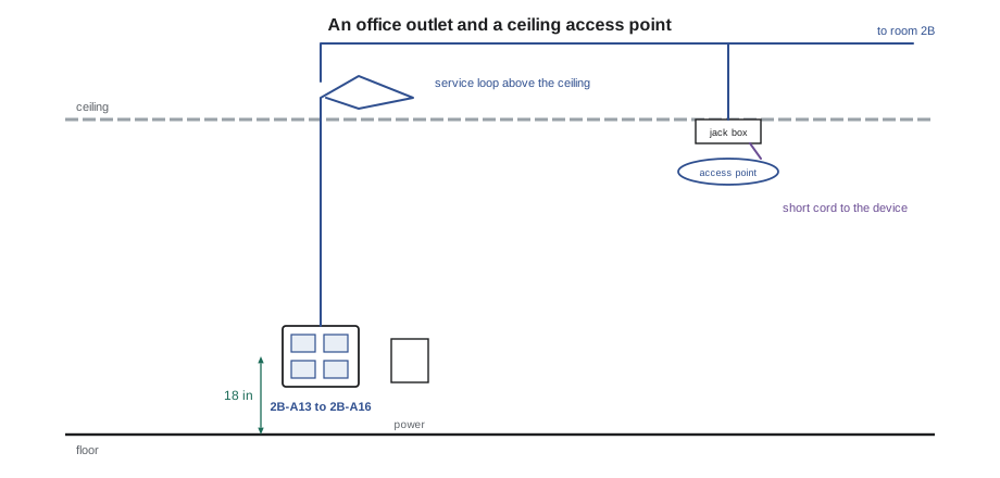
Hospitals show how specialized outlet requirements can become. At St. Brendan's, each patient room has outlets in the headwall behind the bed for the nurse call and patient monitoring systems, at the caregiver workstation, on the wall opposite the bed for the television and patient entertainment system, and in the ceiling for a wireless access point, with counts and locations set by the hospital's standard and by TIA-1179's guidance for healthcare. The outlets in the headwall are mounted in the manufacturer's headwall unit, among medical gas outlets and electrical receptacles, and Maya learns to coordinate their positions with the headwall supplier before rough-in.
Cords and the work area
Cords complete the channel. Patch cords connect panel ports to each other in a cross-connect; equipment cords connect panels to switches; work area cords connect outlets to devices. All of them must be of the same category as the installed cabling, factory-made and tested, and of the right length: long enough to route neatly through the cable managers, short enough to avoid tangles and to stay within the 10 m cord allowance. A cord that is too long ends up coiled in a cable manager or on the floor, and a cord that is too short pulls on the jack.
Cords are the weakest part of any channel because they are handled every day. They are crushed by chair casters, bent sharply behind desks and pulled out by the cable instead of the plug. A failing cord is the most common cause of a desk losing its connection, and the first thing Dev checks on a service call. That is also why the horizontal cabling is tested as a permanent link without cords: the contractor guarantees the permanent part, and the cords are replaceable.
Worked problem
A classroom outlet plan at Riverside
Riverside's board standard gives each classroom: two data outlets at the teacher's station, one at the interactive display, one for a printer, a ceiling outlet for the projector or display controller, one wireless access point in the ceiling, and a camera outlet in the corridor outside the door. How many horizontal cables does one classroom need, and what should Maya check before rough-in?
Show solution
- Count the cables: two at the teacher's station, one at the display, one for the printer, one for the projector, two for the access point (the board requires two cables to each access point) and one for the corridor camera, eight in all.
- Check heights against the drawings: the teacher's station outlets beside the receptacles, the display outlet at the height shown on the display mounting detail, the ceiling outlets at the device locations.
- Check the faceplate and box types: a four-port faceplate at the teacher's station, single ports elsewhere, surface-mount boxes at the ceiling device locations.
- Check that every cable will reach the telecommunications room within 90 m, especially classrooms at the ends of the wings.
Answer: Each classroom needs eight horizontal cables; Maya confirms heights, box types and route lengths before the wall board goes up.
Choosing connecting hardware
On a warranted job, connecting hardware is chosen by the manufacturer's system, not piece by piece. Sanjay specifies one product line of jacks, panels and cords matched to the cable, and the warranty registration lists them. Within that line, he chooses the details that suit the job: angled panels where rack space is tight and vertical managers are generous, keystone-style panels where jacks may need individual replacement, tool-less jacks for crews terminating large numbers quickly, shuttered jacks in dusty spaces and jacks in colors that match the owner's system color scheme. For devices in the ceiling, he chooses between a surface-mount box with a jack and a field-terminated plug, following the owner's preference and the test method the warranty accepts.
Outlets in special environments need special hardware. Outlets in kitchens, washrooms and outdoor locations need covers or sealed jacks; outlets in hospital patient areas may need antimicrobial faceplates that tolerate cleaning chemicals; and outlets in industrial spaces may need ruggedized connectors with sealing gaskets. Each still terminates the same four-pair cable to the same wiring scheme.
Before any jack is terminated on a job, Dev has the crew agree on three things written on the work order: the wiring scheme, the product line and the label format. Problems with any of the three are cheap to prevent and expensive to fix after a few hundred jacks are installed.
Common mistakes
MistakeTerminating one end of a link T568A and the other T568B.
InsteadUse the job's scheme at both ends; check the first jacks against the work order.
MistakeReading the wrong row of color codes on a dual-printed jack.
InsteadKnow which row is A and which is B, and keep to one.
MistakeUsing a Category 5e jack on Category 6A cable.
InsteadAll components of a channel must be the same category, and matched on warranted systems.
MistakeMaking field patch cords from solid horizontal cable.
InsteadUse factory-made, tested stranded cords.
MistakeMounting outlets before confirming device heights.
InsteadCheck heights against the drawings and the accessibility rules before rough-in.
Summary and key terms
- The eight-position modular jack and plug, called RJ45, terminates almost every horizontal channel.
- T568A and T568B differ only in swapping the orange and green pairs; both ends of a link must match, and T568A is TIA's preferred scheme.
- Cords are wired straight through and must match the category of the cabling.
- Horizontal cables terminate on patch panels in the telecommunications room; voice backbone uses 110 blocks.
- Outlets use faceplates, surface boxes, floor boxes or furniture plates, at heights set by the drawings and accessibility rules, labeled with their identifiers.
- Cords are the most handled and most fragile part of the channel, which is why the permanent link is tested without them.
- Eight-position modular connector
- The jack and plug used on twisted-pair channels, commonly called RJ45.
- T568A / T568B
- The two TIA pin and pair assignments for an eight-position jack.
- Insulation displacement contact
- A slotted contact that cuts through a conductor's insulation when the conductor is pressed in.
- Patch panel
- A rack-mounted frame of jacks on which horizontal or backbone cables terminate.
- 110 block
- A punch-down block used for voice backbone and cross-connect jumpers.
- Faceplate
- The plate at an outlet that holds one or more jacks.
- Work area cord
- The cord between an outlet and a device.
Practice problems
Work each problem on paper first, then reveal the answer to check.
Which pairs swap places between T568A and T568B?
Show answer
The orange and green pairs (pairs 2 and 3).
A tester reports pins 1-2 swapped with 3-6. What happened?
Show answer
One end was terminated to T568A and the other to T568B: crossed pairs.
Why are jacks matched to a category?
Show answer
Their internal compensation is designed to cancel the crosstalk of the plug at that category's frequencies.
What block is used for voice backbone cross-connects today?
Show answer
The 110 block.
Why is the permanent link tested without cords?
Show answer
Cords are replaceable and unknown at the end of the job; the contractor guarantees the permanent part.
Lesson quiz · 5 questions
Score 60% or more to complete this lesson.
Create a free account to save your progress, take quizzes and earn a certificate.